UTRGV / COLLEGE OF
ENGINEERING AND COMPUTER SCIENCE / MECHANICAL ENGINEERING DEPARTMENT
TEAM 9 - Design of a Mechanical Mesquite Bean Harvester
Design Process Page


|
SDII Students (L-R) |
o Paul Silva o Miguel
Martinez o Benjamin
Huerta o Joshua
Sanchez
|
|
Faculty Advisors |
o Dr. Arturo Fuentes o Dr. Joanne Rampersad-Ammons
|
|
Course Instructors |
o
Dr. Noe
Vargas Hernandez o
Mr. Greg
Potter |
|
College of Business and Entrepreneurship Collaboration |
o
Dr. Sylvia
Robles (Instructor) o Daniel Castillo o Felipe Montemayor |
Back
to the PROJECT MAIN PAGE.
The Design Process involves several
critical steps that allow for a thorough analysis of the design. This is a non-linear,
iterative process; meaning there are constantly changes/revisions being made to
each step. During Senior Design, we followed a design process which facilitates
an effective and productive problem-solving process. A brief summary of each
step in the design process is listed below, followed by a detailed explanation
pertaining to each step.
Problem ID - Identify a valuable opportunity.
Problem Formulation - Clearly define the problem to solve.
Conceptual Design - Come up with ideas to solve the
problem.
Embodiment Design - Realize the idea.
Testing and Validation - Make sure it works.
The objective of the Problem ID
stage is to identify a valuable opportunity.
The challenge here is identifying a
real problem that the team can help solve. The first step is the brainstorming
phase, where many ideas are put forth and examined. Whether or not each of these
ideas have potential (value opportunity), the process of generating problem
ideas provides an incentive for the team to start thinking about how to solve them.
Once a value opportunity is identified, the next step is to elaborate why such
opportunity exists. This is done by putting together a value proposition, which
explains why the product would be valuable. A product opportunity gap is then
developed to detail how our product could solve the problem at hand (how it
works, technology used, etc.). In addition, a Value Opportunity Analysis is
conducted to evaluate how our proposed solution compares to products within the
current market.

Product
Opportunity Gap (POG)
Our preliminary idea is to utilize
the concept of a rotating unbalance to design a vibrating mechanical device that
exerts a range of driving frequencies equal to that of the natural frequency
range of the mesquite bean pods attached on tree branches. Because not all
mesquite bean pods have the same natural frequency (based on geometry, size,
density, etc.), the rotating unbalance will have to sweep through a range of
natural frequencies. The excitation of the mesquite bean pods will result in
resonance, thus causing the mesquite bean pods to fall from the branches with
ease. Because the proposed device is aimed at exciting the mesquite bean pods
themselves, the mechanism will be mounted on a tree branch, after which the
forced vibrations will propagate through the branch and onto the hanging bean
pods. This approach provides a considerable advantage over hand-picking each
mesquite seed pod individually since it's able to discharge dozens of mesquite
beans at a time, requires relatively no manual labor/input, and eliminates the
possibility of someone getting injured by the long thorns on mesquite tree branches.
Expediting the harvesting process allows for a massive yield of mesquite beans
and therefore enables the business at hand to expand towards mass production of
mesquite bean products.
|
Figure 1 - Rotating Unbalance
Mechanism Sketch |

Value
Opportunity Analysis (VOA)
For the selected POG we created VOA
charts to evaluate our proposed solution to that of current mesquite bean
harvesting methods as well as similar devices currently in the market. These
charts give us an idea of how much of an improvement a mechanical harvester is
over hand picking, in addition to how it compares to that of similar devices.
Team 9 - Ripple Effect
|
ATTRIBUTES |
LOW |
MED |
HIGH |
|
Affordability |
|
|
x |
|
Sustainability |
|
|
x |
|
Quality |
|
|
x |
|
User Friendly |
|
|
x |
|
Aesthetics |
|
x |
|
|
Efficiency |
|
|
x |
|
Safety |
|
|
x |
Hand Picking (Current Method)
|
ATTRIBUTES |
LOW |
MED |
HIGH |
|
Affordability |
|
|
x |
|
Sustainability |
|
|
x |
|
Quality |
|
|
x |
|
User Friendly |
|
|
x |
|
Aesthetics |
|
x |
|
|
Efficiency |
x |
|
|
|
Safety |
x |
|
|
|
Figure 2 - Cappadona Family Hand-picking Mesquite Beans |
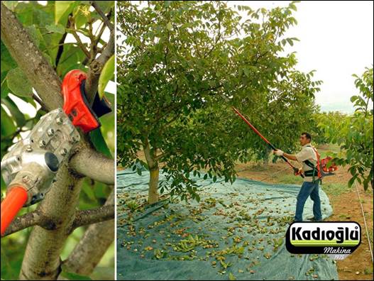
Kadioglu
EMR400 Branch Shaker
|
ATTRIBUTES |
LOW |
MED |
HIGH |
|
Affordability |
|
x |
|
|
Sustainability |
|
|
x |
|
Quality |
|
x |
|
|
User Friendly |
|
x |
|
|
Aesthetics |
|
x |
|
|
Efficiency |
|
x |
|
|
Safety |
|
|
x |
|
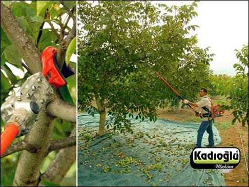
Figure 3 - Kadioglu EMR400 Branch
Shaker |
Yuki Farm Harvesting Machine Orchard
Fruit Tree Shaker
|
ATTRIBUTES |
LOW |
MED |
HIGH |
|
Affordability |
|
|
x |
|
Sustainability |
|
|
x |
|
Quality |
|
x |
|
|
User Friendly |
|
x |
|
|
Aesthetics |
|
x |
|
|
Efficiency |
|
x |
|
|
Safety |
|
|
x |
|
Figure
4 - Yuki Farm Harvesting Machine Orchard Fruit Tree Shaker |

FINAL
PROBLEM STATEMENT
There is a direct need for a mesquite
bean harvester capable of expediting the mesquite bean harvesting process in a
safe and efficient manner.

The objective of the Problem
Formulation stage is to clearly define the problem to solve.
This section involves getting a
better understanding of the problem we are trying to solve by conducting
research on relevant topics, analyzing the performance of existing products, identifying
the main user of our solution (as well as the value for the user), determining
initial customer segment, and generating a design specification (list of
requirements). These subtasks within problem formulation will help the team get
a clear understanding of the problem to solve.
BACKGROUND
RESEARCH
To better understand the context of
the problem to solve, we conducted Background Research on the following topics:
o
Mesquite
Trees
o
Mesquite
Beans
o
Frequency
Response of Trees
o
Mechanical
Properties of Trees
o
Mechanical
Stability of Trees
o
Analysis
Methods
o
Vibrating
Machinery (Rotating Unbalance)
o
FEA
Modeling and Material and Geometric Properties (Numerical Methods)
o
Mechanical
Harvesting
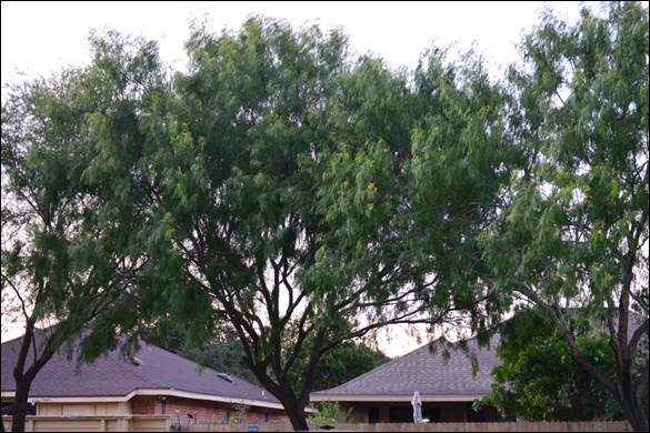
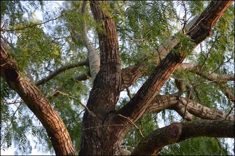
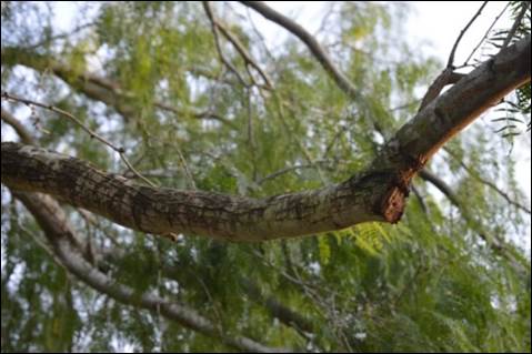
Figure 5 - Mesquite Tree at Park
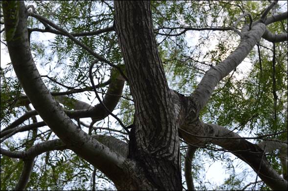
Figure 6 - Branch Complexity
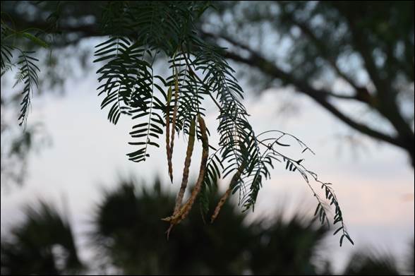
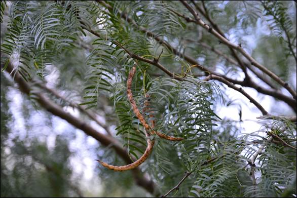
Figures 7 & 8 - Mesquite Beans on Branch
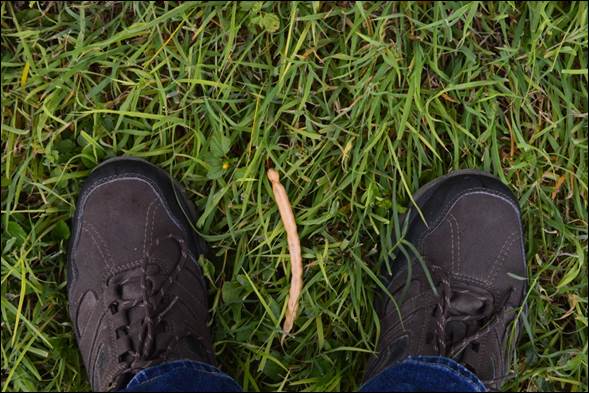
Figure 9 - Fallen Mesquite Bean
COMPETITIVE
PRODUCTS
To avoid "reinventing the wheel",
we looked at existing solutions and competitive products.
Listed
below are the closest competitors for the task at hand. Although there are no
dedicated mesquite tree harvesting devices, there are devices which are used to
harvest other products in a similar manner.
1. Tractor Attachment
Savage Shaker
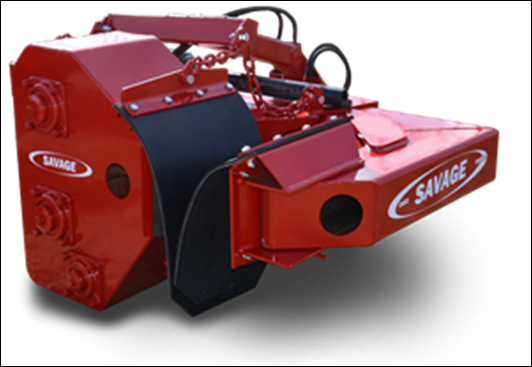
Figure
10 - Savage Shaker
Click HERE to View Product Website.
Description -
This pecan tree shaker was the first piece of machinery developed at Savage, as
well as the first of its kind for the nut-harvesting industry. Savage Shakers
have evolved into finely crafted, rugged machines, and they now help growers
get the job done on many parts of the globe. The Savage shaker can shake almost
any tree. The machine is available in various sizes, with each model capable of
shaking a wide range of tree sizes.
Advantages
- The
shaker attachment is ruggedly built. Savage Shakers feature heavily braced and
reinforced clamp arms; easily removed bearings and simple access to shaking
components; oversized adjustable drive chains; and easily changed tree pads.
Disadvantages -
The savage shaker is a tractor attachment, meaning it requires a tractor with a
PTO (Power take-off) to function. It also requires a certain amount of PTO or
HP (Horsepower) to produce the proper vibration, depending on the size of the
tree. This can be a problem if one's tractor does not generate enough power for
the shaker attachment.
2. Shaker & Collector
MultiOne Tree Shaker &
Collector

Figure
11 - MultiOne Tree Shaker & Collector
Click HERE to View Product
Website.
Description -
The tree shaker attachment incorporates the most advanced harvest technology
for olives, almonds, nuts, pistachio, etc. The shaker requires a minimum
distance of 70 cm (27 in) from the soil to the foliage. The adjustable
vibration frequency maximizes the effect on the fruit, avoiding low frequency
vibrations on the trunk. The hydraulically controlled collector has a diameter
of 5 m (16.4 ft), capturing fruit from large trees and is equipped with a
hydraulically opening hatch through which is possible to unload the product
collected directly on trucks or trailers. The shaker vibrating head is powered
by a compact hydraulic motor and it is tiltable to the right and to the left (�
40�).
Advantages
- Total
control of vibration frequency allows for shaking different trees at different
frequencies. Very efficient machine. Depending on ground conditions, as many as
40 to 60 trees can be processed per hour. Has a wide collector to catch fruit
from large trees. Operates on trees with wide trunks. Can adjust vibrating head
to shake at different angles. Shaker's controls are located near the operator's
seat and controls all movements and vibration frequency. Combines shaking
device with collection system.
Disadvantages -
Adjustable vibration frequency has a limit of 40 Hz. Tree Shaker and Collector
attachment requires MultiOne Mini Loader Vehicle. Tree Shaker & Collector
is not universal (not compatible with other tractors).
3. Mobile
Shaker
Kadioglu
EMR400 Branch Shaker Harvesting Machine
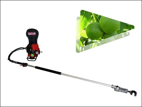
Figure
12 - Kadioglu EMR 400 Branch Shaker Harvesting Machine
Click HERE to View Product
Website.
Description -
The Kaidoglu EMR400 features a handheld hook-shaped gripping mechanism which
delivers high frequency vibrations to cause fruit to fall. It utilizes a
gasoline engine with 2.6 horsepower. The motor is worn on the back of the user
and has a mass of about 9.5 kg (about 20 pounds) while the hook mechanism has a
mass of 2.5 kg (about 5.5 pounds). This device is intended for use on walnut
tree branches with height up to 4 meters and thickness of 3 cm. In case of
failure, the device is modular, and parts can be replaced.
Advantages
- Engine
can be worn as a backpack which makes the device very mobile (Motor weight: 9.5
kg). Can be used on almost any type of tree. Does not require a large power
input. Gasoline motor has high price/performance ratio. Long arm can reach
branches that are high up in trees. Relatively easy to use (trigger activated).
Disadvantages -
For very large, tall trees, extender arm may not be able to reach branches that
are very high up. Grip width is not adjustable. Can only grab onto branches
that are 3 inches thick or less. Unbale to adjust frequency of vibration.
4. Shaker Vehicle
OMC Shockwave Sprint VI
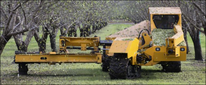
Figure
13 - OMC Shockwave Spring VI
Click HERE to View Product
Website.
Description -
The latest version of OMC's Shockwave Sprint tree shaker makes life easier by
boosting the harvest efficiency for farmers growing almonds, walnuts, or young
pecans. The key to the Sprint's high performance is its side-mounted shaker
which allows the operator to glide down the row and shake up to 7 trees per
minute. The all-new R-7 Magnum shaker head with 24-inch oval pads and automatic
sling lubrication is standard, providing powerful shaking performance in a
compact package that effortlessly moves through dense plantings. Movement is
provided by a hydrostatic drive with a 19-1 ratio, with a 24-1 ratio available
as a no-cost option. LED night lights illuminate the front, side and rear of
the vehicle, while a color monitor provides crucial information and settings
inside. Heating and air-conditioning are standard, for more comfortable and
productive days in the field.
Advantages
- No
attachments needed. Shaking mechanism is integrated into vehicle. Contains a
comfortable cabin with air-conditioning and heater. Equipped LED lights allow
for nighttime harvesting. Shaker is mounted on side to allow clear visibility
for driver. The side-mounting for efficient harvesting since driver can simply
drive up a row, shake each tree, without having to maneuver from side to side.
New shaking technology provides powerful shaking.
Disadvantages -
Heavy duty vehicle (large in size). Almost 19 feet in length and 12 feet wide
(with shaker head retracted). Requires vehicle maintenance.
5.
Collector
The
Original Fruit Collector
Figure
14 - The Original Fruit Collector
Click HERE to View Product
Website.
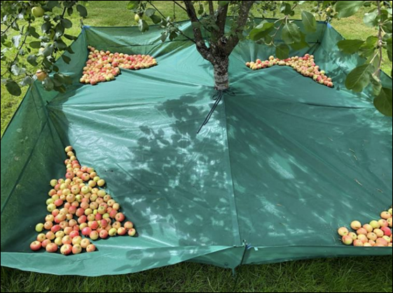
Description -
The Original Fruit Collector is a harvesting net designed to catch fruit fallen
from trees while protecting the fruit from dirt and bugs. It is advertised to
softly catch fruit from all fruit trees without bruising the fruit, including
apples, cherries, and others. The mesh design allows water and air to travel
through while keeping the fruit from rolling out of the enclosed area, thus
keeping the grass healthy. It is available in different sizes to suit
individual needs. It requires assembly from the user.
Advantages
- Rapid
set up can be achieved in a few minutes. Can be affixed to a pole or similar
structure instead of a tree if desired. Polyester fiber material is durable and
machine washable. Can work passively, the net will catch fruit if the tree is shaken
or if fruit falls naturally.
Disadvantages -
The collector is set up low to the ground, potentially creating difficulties if
the user wishes to manually shake the tree. Once set up, the fruit collector is
designed to stay in its place for long periods of time. If the user has
multiple trees to harvest from, they will need to purchase multiple collectors
or manually move it from tree to tree.
USER
RESEARCH
Understanding the user wants and
needs is key for the design of a valuable product. We applied a variety of User
Research techniques for that purpose.
In
this case, our main user will be farmers with medium-sized ranches in Texas who
harvest mesquite beans for mass production of a product. For example, the
Cappadona Ranch harvests mesquite beans and is looking to mass produce mesquite
products for grocery stores & supermarkets to sell. Current mesquite bean
harvest techniques involve manual picking which requires high labor intensity
and is not very efficient. Although this process works well enough to sell
mesquite bean products locally, continuing to hand-pick mesquite bean beans
will not allow their business to grow and expand beyond what it is currently
(local small business). The Cappadonas are looking to expedite the harvesting
of mesquite beans and transition towards a more efficient technique. This will
give their business an opportunity to sell mesquite bean products at a much
larger scale. Efficiency and productivity are two things the Cappadona family
is seeking in a new and improved harvesting technique. A mechanical mesquite
bean harvester will bring exactly that.
Cappadona
Ranch Visit
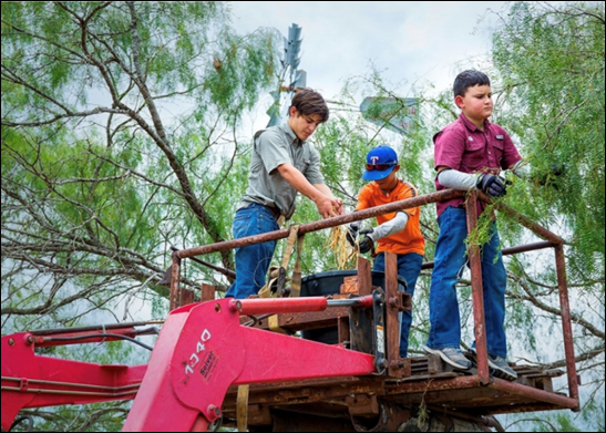
o Harvesting Rate
Currently, with the family handpicking the mesquite beans from the tree for long hours, they are able to harvest approximately 5,000 pounds of mesquite beans annually (200 pounds per day); in order for them to expand their business and partner with HEB, estimates for the required harvesting rate need to be 10 times that amount (~50,000 pounds/year of mesquite).
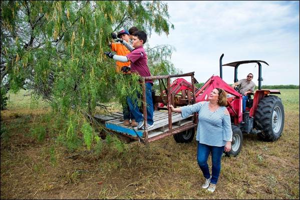
Figure 15 - Cappadona Family on Tractor Platform
Picking Beans by Hand
o Benefits
and Nutritious Value
The
mesquite bean has a unique set of nutritious value that makes it a very healthy
addition to almost any meal. The bean is a superfood that can manage glucose
levels for those who consume it. Mesquite beans can be turned into a variety of
products such as jelly, coffee, flour, tea, bread, and soap. The flour made
from mesquite beans contains natural sugar with high fiber and protein content
that makes it diabetic friendly. In addition, the mesquite bean flour can be
used as a sugar substitute or as a seasoning. When the mesquite tree is roasted
and grounded it makes a great coffee substitute (naturally caffeine free). The
mesquite bean has a wide range of food benefits that can change the way people
eat.
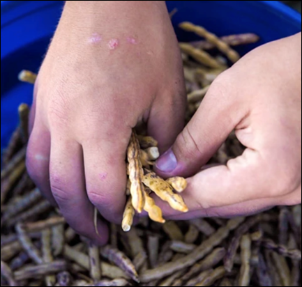
Figure 16 - Collected Mesquite Beans
o Impact
on other Farmers
Texas
farmers with lots of mesquite trees on their property often contact Cappadona
Ranch about coming to pick mesquite beans off their trees. However, Cappadona
Ranch is not interested in picking beans on other properties, they are only
interested in the beans themselves; meaning the farmer needs to go out and pick
the beans off the trees themselves. Because the task of handpicking mesquite
beans is too labor intensive & time consuming for many of these farmers,
they are not able (or willing) to put in the work needed to handpick mesquite
beans. However, with a mechanical harvester, this task will become much easier
to accomplish. Farmers across south Texas will now be able to harvest mesquite
beans off their trees and sell them to Cappadona Ranch for ~$2/pound. This
would become a relatively easy job for many farmers willing to make some money from
their mesquite trees.
o
Mechanical Harvester Chain Reaction
The number one reason why Cappadona Ranch is unable to mass produce their mesquite bean products is the inefficient technique of hand-picking mesquite beans. They simply aren't able to harvest enough mesquite beans to produce enough products for mass production and distribution to grocery stores and supermarkets across the state. Hand-picking mesquite beans is restricting their business from continuing to grow and expand beyond the community level. A mechanical harvester would remove this constraint in the mesquite harvesting process and allow for a significant increase of harvested mesquite beans. This breakthrough will then allow for the mass production of mesquite bean products to markets like HEB and others. Having mesquite bean products on supermarket shelves is a big deal. Mesquite bean products are natural, healthy, and positively affect people's health. This is a superfood that has yet to reach its full potential. Having a wider range of customers learn more about the benefits of mesquite bean products will result in more and more people wanting to consume such products. From a food production perspective, mesquite bean products can have a huge impact. Increasing the amount of harvested mesquite beans will allow for new mesquite bean products to be created. The Mesquite Tree is a nutritious food source that is underutilized. A mechanical mesquite bean harvester will change how the mesquite tree is viewed and used.
To Learn More about Cappadona Ranch,
Click HERE.

Figure 17 - Cappadona Ranch Logo
DESIGN
SPECIFICATION
The Design Specification captures
the "essence" of the design. The following table shows the Design
Spec for our project.
The design specifications are subject to change as more information is discovered about the problem. The current design specifications are estimates concerning the final design of the product. If possible, these specifications will be met. Once more information through testing has been performed, the team will determine if the design specifications are feasible.
|
UTRGV |
Rev. 01 |
Design Specification (Requirement List) for the Design of a Mechanical Mesquite Bean Harvester |
Issued on: |
|
Changes |
D/W |
Specifications |
Responsible |
|
2/28/2021
2/28/2021
2/28/2021
2/28/2021 |
D
D
D
D |
Geometry - General Mechanical Harvester Dimensions Rotating Unbalance Assembly (lwh): 20 cm x 20 cm x 20 cm Compact Motor design Extender Arm Assembly (length): 4 m Long enough to reach high branches - General Collector Dimensions Canopy (Full-Spread) Radius: 2 m Large catch diameter; Wide enough to catch fallen mesquite beans from consecutive branches Canopy Carrier (lwh): 1 m x 0.75 m x 0.75 m Mobile, compact. Easy to move around |
MM
MM
MM
MM |
|
2/28/2021 2/28/2021 2/28/2021 2/28/2021
2/28/2021
2/28/2021 2/28/2021
2/28/2021 2/28/2021 2/28/2021
2/28/2021 2/28/2021 |
D D D D
D
D D
D D D
D W |
Components - Rotating Unbalance Mechanism Two (high-speed) motors (w/offset masses) (Bluetooth?) Battery Electronics Mount Platform for motor, battery, electronics Adjustable Strap Help secure to branch (up to 10 cm diameter) - Extender Arm Pole Grip Improve control; prevent slippage - Collector Canopy Carrier Off-road Wheels Mobility in rough terrain Storage Latch door Help release/transfer mesquite beans into another container |
MM MM MM MM
MM
MM MM
MM MM MM
MM MM
|
|
2/28/2021
2/28/2021
2/28/2021
2/28/2021
2/28/2021
2/28/2021
2/28/2021
2/28/2021
3/2/2021
3/2/2021
3/2/2021
|
D
W
D
D
W
W
D
W
W
D
D |
Features - Rotating Unbalance Mechanism Frequency Control Adjust frequency according to branch/beans Detachable from Extender Arm Can be attached and placed on branch manually Display Screen showing information (Battery percentage, Frequency, etc.) - Extender Arm Retractable Compact, easy storage Power Button to activate Rotating Unbalance - Collector Retractable Canopy Easy storage when not in use (can be removed/stored) Manual Deployment Using string/rope Automated (Electronic) Deployment Using electronics/motor Adjustable Tarp/Funnel Angle Wide/Narrow Collection Area Easy Access to Bean Pod Storage Once bean pod storage container is full, remove, and put in a new one. Or empty into other container & insert back. Wind-Resistant Does not sway. Remains stationary when in use. |
MM
MM
MM
MM
MM
MM
MM
MM
MM
MM |
|
2/28/2021
2/28/2021 2/28/2021
|
D
W W |
Kinematics - Rotating Unbalance Mechanism MAX Amplitude of Vibration: 10 cm - Collector 4 or 6 Bar mechanism for deployment Origami-inspired deployment
|
MM
MM MM
|
|
2/28/2021
2/28/2021
|
D
D |
Forces Generated Force Range: 10 N - 25 N Capable of generating enough force to excite beans Vibration Resistant Mechanism capable of withstanding heavy vibrations
|
MM
MM |
|
2/28/2021 2/28/2021 2/28/2021 2/28/2021
|
D D W W |
Energy Powered by Rechargeable Battery Battery Life lasts 8-10 hours. Electronics encased Does not overheat
|
MM MM MM MM |
|
2/28/2021
2/28/2021 2/28/2021 2/28/2021
2/28/2021 |
D W
D |
Materials - Rotating Unbalance Mechanism Strong, flexible materials Capable of withstanding heavy vibrations Waterproof Tough, thick tarp Does not easily rip from thorns |
BH MM BH
BH BH JS |
|
3/1/2021 3/1/2021 3/1/2021 3/1/2021 |
D D D W
|
Signals Frequency adjustment via (?) Electrical control of motor speed Feedback signal to measure Amplitude/Frequency Remote-controlled
|
PS PS MM PS
|
|
3/1/2021
3/1/2021 3/1/2021 3/1/2021
3/1/2021 3/1/2021
|
D
D D D
D D/W |
Safety Vibrations should be effective but also not damage the tree bark No physical interaction with the mesquite tree thorns Ease of installment/removal Mesh net canopy will prevent contamination that occurs when the mesquite beans contact the ground Canopy material mitigates the impact of the falling seeds Safety Factor: 3
|
PS
PS PS PS
PS MM |
|
3/1/2021
3/1/2021 3/1/2021
3/1/2021
3/1/2021 3/1/2021
3/1/2021 |
D
D D
W
D D
D |
Ergonomics - Rotating Unbalance Mechanism Lightweight (< 8 kg) - Extender Arm Lightweight (5-10 kg) Rubber grip handle (shaped) Comfortable for user Adjustable in length (up to 4 m) - Collector Adjustable clamp/grip/rope/canopy Funnel-shaped collection mechanism for fallen mesquite beans to roll in together Secure, compact, transportable, and easy-to-setup collection canopy Sort out good and bad mesquite beans when in use
|
PS
PS MM MM MM
PS PS
PS
JS
|
|
3/1/2021 3/1/2021 3/1/2021
3/1/2021 |
D D D
D |
Quality Control Experimentally tested (for performance) ASTM, ANSI Approved High quality materials For extended use Collecting as many beans as possible |
MM MM PS
JS |
|
3/1/2021 3/1/2021 3/1/2021 3/1/2021 3/1/2021 3/1/2021 3/1/2021 |
D D D D D D |
Assembly Securely assembled Vibration resistant screws Washers Motor mounts Velcro strap Adjustable sleeve/strap
|
PS PS PS PS PS PS |
|
3/1/2021 3/1/2021 3/1/2021 |
D D D
|
Operation Remote controlled or tractor attachment installed/controlled Precision in frequency settings Simple maneuverability controls |
PS PS PS
|
|
3/1/2021 3/1/2021 3/1/2021 3/1/2021 3/1/2021 3/1/2021 3/1/2021 3/1/2021 |
D D D D D D D |
Maintenance Replaceable parts Long life cycle (approx. 6-8 years) Replace motor every 4 years Ensure clean electronics compartment Check for wiring quality Recharge battery after every use Clean
canopy/canopy storage |
MM MM MM MM PS MM PS JS |
|
3/1/2021 3/1/2021 3/1/2021 |
D D D |
Costs Extremely low cost, approximately $500 High quality materials Cost
efficient (should effectively harvest mesquite beans) For Ranchers/Farmers harvesting mesquite beans |
PS PS PS JS |
The objective of the Conceptual
Design stage is to come up with ideas to solve the problem.
Here, the team is tasked with
generating effective ideas to solve the problem. This process involves defining
the overall function of the proposed solution (can be broken down into
subfunctions), finding individual solutions to each subfunction (explore "design
universe"), collecting solutions on morphological chart, creating and
evaluating combinations of solutions (concept variants), and finally, selecting
the final concept based on a thorough analysis of the generated concept variants.
FUNCTIONAL
DESIGN
Creating a Functional Diagram allows
us to understand what the product is going to do, and not
necessarily how. This allows the team to explore different
options for each subfunction within the functional diagram.
|
Figure 18 - Functional Diagram
(Excitation)
|


Click HERE to
View our Functional Diagram (Excitation & Collection).
MORPHOLOGICAL
CHART
The Morphological Chart helps us
explore the "design universe" for possible solutions to each subfunction.
This way, it helps the team focus on one subfunction at a time and find
individual solutions for each corresponding subfunction.
Below is a list of the different
subfunctions involved within the two components of the design (Excitation &
Collection). For each subfunction, the team has identified various possible
components that can perform the specified task.
EXCITATION
SF1 - Wireless Communication
SF2 - Electric Control Module
SF3 - Generator of Vibration
SF4 - Transmits Vibrations to Branch
SF5 - Excites Mesquite Bean Pods
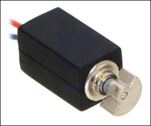
Figure
20 - "Generator of Vibration" Potential Solution (Rotating Unbalance)
COLLECTION
SF6 - Funnel (Guide) Fallen Mesquite
Bean Pods
SF7 - Stores Fallen Bean Pods
SF8 - Transports Harvested Bean Pods
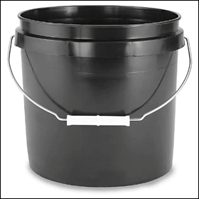
Figure
21 - "Stores Fallen Bean Pods" Potential Solution (Storage Bucket)
Click HERE to
View our Morphological Chart (Excitation & Collection).
CONCEPT
VARIANTS AND SELECTION PROCESS
After coming up with a variety of
solutions to address each subfunction, the team must now make combinations of
solutions for each subfunction and create concept variants. These variants will
be evaluated accordingly to identify the top solution variants.
Click HERE to View our Concept Variants.
FINAL
CONCEPT(S)
After the selection process we
arrived at the Final Concept.
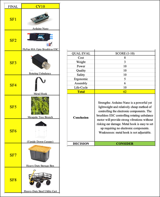
Figure
22 - Final Concept Variant (CV10)
The objective of the Embodiment
Design stage is to realize the concept by performing the appropriate analysis.
This is an iterative process in
which the team continues to make the concept more real. Here, the technical
aspects of the design are addressed by applying our engineering knowledge. In
this case, such calculations and analysis will involve several engineering
subjects including Mechanical Vibrations, Dynamics, Mechanics of Solids, Machine
Elements, and Finite Element Analysis (FEA).
STRATEGIES
AND PRIORITIES
Starting from our final concept(s), the
team identified the necessary analyses and engineering work to realize the
concept into a product.
o
First
off, the team went ahead and created the components needed to construct the
motor assembly on solid works. From these parts, the team put together two different
motor assemblies.
o
Next,
different offset mass geometries were investigated to examine how different
shapes affect the magnitude of the generated force.
o
Furthermore,
the team carried out the proper analysis on these two assemblies to evaluate
and determine which assembly we should move forward with. The forces generated
by all four offset mass geometries at both natural frequencies (8 Hz & 24
Hz) were calculated first. Then, motor assembly parameters including torque
requirement (to accelerate the offset mass and the shaft), expected pillow
block forces, and bending stresses throughout the length of the shaft were
evaluated accordingly.
o
The
team then modified the SolidWorks components created according to the materials
that were purchased. In addition, different mounts were designed and
implemented into the assembly (to attach to hook). Here, the team determined it
was best to redesign the hook and allow for a more compatible branch-hook
interface. The old hook had a fixed width and could only be latched onto
branches of one specific size.
o
After
that, the team took important measurements from mesquite tree branches (at
Zinnia Park). To make the new hook more compatible, we measured the
circumference of various mesquite tree branches. From this data, a minimum,
maximum, and average diameter was computed.
o
The
team then redesigned the hook on SolidWorks based off the branch measurements
recorded. This new hook design features a tapered interface which should help
it grab on to a wide range of branch sizes.
o
A
Finite Element Analysis was performed on the Hook to investigate the effects of
the transmitted force on a hollow hook (deflection). The team wanted to know if
a hollow hook could handle the expected vibrations from the offset mass.
o
Before
proceeding to the machining phase of the project, the SolidWorks assembly model
was updated. This gave the team a better idea of where each component is placed
and how the device functions.
o
After
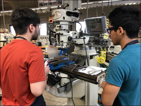
coming up with the drawings for each component, the team began the machining
process at the Machine Shop at UTRGV. Since this device is the first of its
kind, many of its components are custom made. This includes the mounts, hook
frame, and offset masses.
o
Once
the machining was completed, the team focused on setting up the electronics and
mounting them on the hook/pole. Both the batteries and speed controller
required 3D printed cases/housings.
o
Other
accessories were then introduced to the device including new pole grips, rubber
pads for the inside of the tapered hook section, wire tubing (protect wires),
and a clamp mount to attach the speed controller case to the pole.
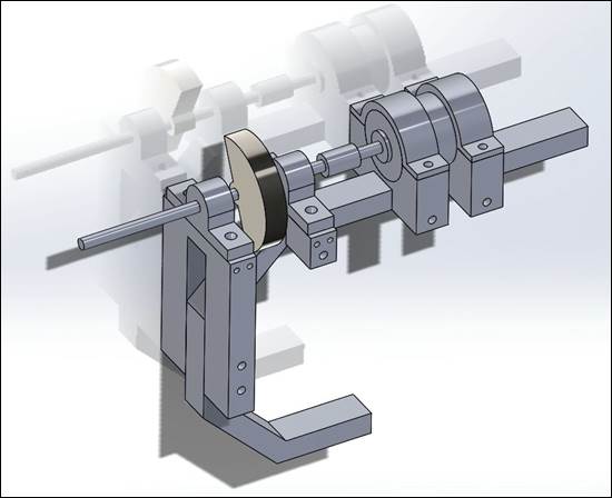
TASK
1 - MOTOR ASSEMBLY MODELING
Click HERE to View Motor Assembly Components.

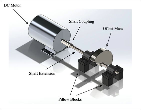
Figure
23 - Motor Assembly 1
Figure
24 - Motor Assembly 2

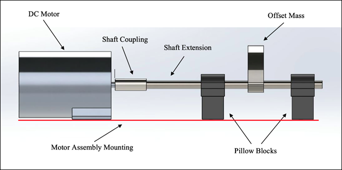
Figure
25 - Motor Assembly 1 (SIDE)
Figure
26 - Motor Assembly 2 (SIDE)
TASK
2 - OFFSET MASS GEOMETRIES
|
|
|
|
Figure 27 - Offset Mass 1 |
Figure 28 - Offset Mass 2 |
|
|
|
|
Figure 29 - Offset Mass 3 |
Figure 30 - Offset Mass 4 |

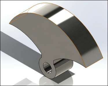
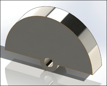
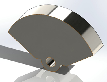
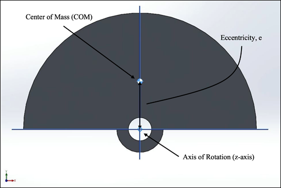
Figure
31 - Offset Mass 3 Labeled (COM, Eccentricity, Axis of Rotation)
The eccentricity is defined
as the distance from the axis of rotation to the center of mass for the
rotating unbalance.
In the figure above, both the center
of mass and the eccentricity are labeled for offset mass 3. For this geometry
and mass distribution, the eccentricity is 1.03 inches from the axis of
rotation (center of the hole that accepts the shaft).
Table 1 - Offset Mass Properties
& Parameters
|
|
Offset
Mass 1 |
Offset
Mass 2 |
Offset
Mass 3 |
Offset
Mass 4 |
|
Material
Applied |
AISI
1020 |
AISI
1020 |
AISI
1020 |
AISI
1020 |
|
Material
Density (lb/in3) |
0.29 |
0.29 |
0.29 |
0.29 |
|
Volume
(in3) |
5.83 |
5.98 |
10.01 |
8.15 |
|
Eccentricity
(in) |
1.36 |
1.39 |
1.03 |
1.18 |
|
Mass
(lb) |
1.66 |
1.71 |
2.86 |
2.32 |
NOTE: The force generated from the
rotating unbalance is linearly proportional to both the offset (unbalance) mass
and the eccentricity, while the force is proportional to the square of the
driving frequency.
TASK
3 - CALCULATIONS & ANALYSES
(a)
ROTATING UNBALANCE OVERVIEW
(Eq. 1) - Equation of Motion for
Rotating Unbalance

(Eq. 2) - Force Magnitude Generated
by Offset Mass
![]()
Click HERE to View Derivation of Equation.
Parameters:
![]() - mass of the system (kg)
- mass of the system (kg)
![]() - damping coefficient (kg/s)
- damping coefficient (kg/s)
![]() - stiffness of the system (kg/s2)
- stiffness of the system (kg/s2)
![]() - offset (unbalance) mass (kg)
- offset (unbalance) mass (kg)
![]() - eccentricity (m)
- eccentricity (m)
![]() - driving frequency (rad/s)
- driving frequency (rad/s)
t - time (sec)
![]() - translational acceleration (m/s2)
- translational acceleration (m/s2)
![]() - translational velocity (m/s)
- translational velocity (m/s)
![]() - translational displacement (m)
- translational displacement (m)

Figure
32 - Rotating Unbalance Diagram
NOTE: As seen in the equation of motion
(Eq. 1), the generated force is directly (linearly) proportional to the mass of
the rotating unbalance and the eccentricity, while being a function of the square
of the driving frequency. Although the mass and the eccentricity do affect
the magnitude of the force, the frequency at which the offset mass rotates has
a much larger influence on the force.
Example
1:
Force generated by small motor (with
two small offset masses) at a driving frequency of 8 Hz.
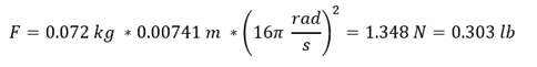
Case of 1 kg mass and 0.1m
eccentricity at a driving frequency of 8 Hz.

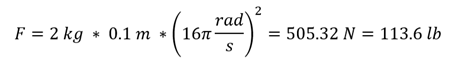
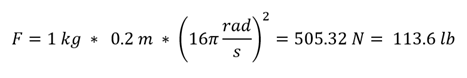
Example
2:
Note that in the case of doubling
either the mass or eccentricity, the force generated is also doubled. Comparing
the following two equations to the case of 1 kg and 0.1 m, the generated force
is doubled.
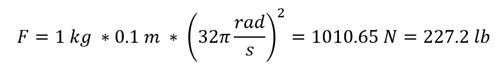
However, because the driving
frequency is squared, doubling the driving frequency quadruples the generated
force.
(b)
FORCE GENERATED BY VIBRATION (OFFSET MASS)
Table 2 - Natural Frequencies of
Mesquite Beans (BENDING)
|
|
First (Lower) |
Second (Upper) |
|
|
8.0486 |
24.045 |
|
|
50.571 |
151.079 |
NOTE: Natural Frequencies of Mesquite
Beans gathered by previous team.
Click HERE to View Conversion of Natural
Frequencies.
![]()
![]()
![]()
NOTE: ![]()
Offset Mass Material: AISI 1020
(Steel)
AISI 1020 (Steel) Density, ![]()
Offset Mass 3
![]() ,
, ![]() ,
, ![]()
![]()
![]()
![]()
NOTE: ![]()
|
|
Generated Force by Offset Mass 3 at ![]()
![]()
![]()
|
|
Generated Force by Offset Mass 3 at ![]()
For Rest of Offset Mass Force
Calculations, Click HERE.
Graphs are shown below depicting the
relationship between the magnitude of the force generated, ![]() , and the different parameters that make
it up (mass of offset,
, and the different parameters that make
it up (mass of offset, ![]() , eccentricity,
, eccentricity, ![]() , and driving frequency,
, and driving frequency, ![]() ). Although the generated force is directly
proportional to both the offset mass and the eccentricity, it is a function of the
square of the driving frequency.
). Although the generated force is directly
proportional to both the offset mass and the eccentricity, it is a function of the
square of the driving frequency.
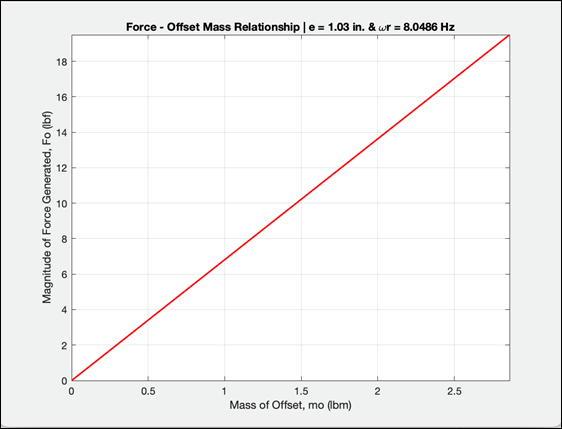
Figure
33 - Force - Offset Mass Relationship
Here, the relationship between the
generated force and the offset mass is shown with constant eccentricity of 1.03
inches (Offset Mass 3) and constant driving frequency of 8.0486 Hz (first
natural frequency). The relationship is linear (constant rate of change). The
magnitude of the force generated increases as the mass of the offset increases.
In this case, the largest force generated (19.497 lbs) occurs at a mass of 2.86
pounds (mass of Offset Mass 3).
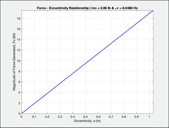
Figure
34 - Force - Eccentricity Relationship
Pictured above is the relationship
between the magnitude of the force generated and the eccentricity of the offset
mass with fixed parameters. The mass of the offset is 2.86 pounds (Offset Mass)
and the driving frequency is 8.0486 Hz (first natural frequency). Similar to the
previous graph, the generated force is directly related to the eccentricity of
the offset mass. As the eccentricity increases, so does the magnitude of the
force generated (linearly). With the mass of the offset and the driving
frequency held constant, the largest generated force is 19.497 pounds at an
eccentricity of 1.03 inches.
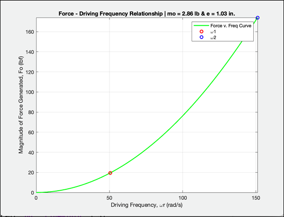
Figure
35 - Force - Driving Frequency Relationship
Unlike the previous two graphs, the relationship
between the generated force and the driving frequency is not linear, but
instead quadratic. In this case, the rate of change increases as the driving
frequency is increased. This way, one can generate a larger force much quicker
by simply increasing the frequency at which the offset mass is spun. This
scenario is more controllable since the physical parameters of the offset mass
(mass & eccentricity) don't have to be adjusted to increase or decrease the
magnitude of the force. Therefore, the team intends on using the driving
frequency as the main parameter to adjust the generated force.
Click HERE To View MATLAB Codes.
(c)
TORQUE REQUIREMENT
Offset Mass 3
Given (SolidWorks): ![]()
Required to reach a speed of ![]() = 8 Hz in
= 8 Hz in ![]() = 3 seconds.
= 3 seconds.
![]()
Angular Acceleration, ![]()
![]()
![]()
Torque, ![]()
![]()
|
|
Required Torque to rotate Offset
Mass 3 at ![]()
To View Torque Requirement Hand Calculations,
Click HERE.
(d)
PILLOW BLOCK FORCES (ASSEM. 1 & 2)
The team is very interested in the
expected (reaction) forces within the two pillow blocks (for both assemblies).
In order to move forward with one motor assembly, the team must compare the
forces within each set of pillow blocks. These calculations will also go a long
way in determining what type of pillow blocks we will end up purchasing. Such
pillow blocks will need to withstand the loads calculated.
By considering the DC Motor as a
fixed support, the shaft extension as a beam, the pillow blocks as journal
bearings, and the offset mass as a point load, one is able to diagram the motor
assembly as a Statics/Mechanics of Solids problem. However, after determining
the number of reactions within the setup, the team realizes there are more
unknown reactions (5) than there are equilibrium equations (3). Therefore, the
structure is considered statically indeterminate.
NOTE: Assume all reactions as positive
Still, there is a way to solve the
problem. By applying the method of superposition, one is able to isolate the
point load (force generated by offset mass) from the each of the two vertical
reaction forces at the pillow blocks. In this case, the two reaction forces at
the pillow blocks are converted into point loads at their respective locations.
Then, it is determined that summation of the deflections at the two pillow block
locations (A & B) due to the three individual loads is equal to zero. With
this, one is able to establish two equations in which the two pillow block
forces (Ay & By) are unknown.
The various deflections can be
calculated by considering the shaft extension as a cantilever beam with
concentrated loads at the end or concentrated loads at any point (using machine
elements booklet). Once both equations have all the appropriate deflections,
one can solve for the two pillow block reactions. Then, using the equations of
equilibrium, the reactions at the fixed support (motor) can be solved for. MATLAB
was used to verify the hand calculations.
The reaction forces at the pillow
blocks for Motor Assembly 1 are both greater than those of Motor Assembly 2. Ay
for Assembly 1 is approximately 1.7x greater than Ay for Assembly 2. On the
other hand, By for Assembly 1 is close to 6x larger than By for Assembly 2.
This is a glaring difference in the pillow reaction forces between the two
motor assemblies. In this case, assembly 1 causes a very large amount of load
to be directed at the pillow block between the offset mass and the other pillow
block.
From these calculations, assembly 1
does not seem ideal to implement. One of the pillow blocks will be carrying a
significantly larger load than the other. In addition, assembly 1 causes the
forces within the pillow blocks to be larger than the load itself (offset mass
force). Although assembly 2 still imparts relatively large reaction forces on
the two pillow blocks, they are a lot less than those within assembly 1.
Click HERE to View Pillow Block Forces
Calculations (Assem. 1 & 2).
Click HERE to View MATLAB Codes.
(e)
BENDING STRESSES IN SHAFT (ASSEM. 1 & 2)
Once the reaction forces at each of
the pillow blocks have been solved for, one is then able to calculate the
(maximum) bending stresses within the shafts of both assemblies. First, the
shear and bending moment diagrams are drawn. Then, since the diameter of the
extension shaft does not change, one is able to calculate the maximum bending
stress by identifying the largest magnitude bending moment on the diagram and
plugging it in into the appropriate bending stress equation.
For a solid round bar- ![]()
![]() - Bending Moment
- Bending Moment
![]() - Diameter of shaft
- Diameter of shaft
|
Assem. 1: |
|
Assem. 2: |
After carrying out the appropriate
calculations, it is determined that the maximum bending stress within the shaft
in assembly 1 is approximately 2.6x greater than the maximum bending stress
with the shaft in assembly 2. Again, since the diameter of the shafts do not
change, one can determine which stress will be larger and by how much just by
looking at the maximum bending moment within the assembly.
After calculating both, the expected forces at the pillow
blocks and the maximum bending stresses within the shafts of each assembly, it
is clear that assembly 2 is the best option. Assembly 2 does not demand an
extremely large reaction force out of one of the pillow blocks and has a
significantly smaller maximum bending stress within its shaft.
Still, further analysis will be conducted to verify these
results and continue gathering more information regarding other aspects of the
motor assembly designs.
Click HERE to View Bending Stress Calculations.
TASK
4 - SOLIDWORKS UPDATE
Figure
36 - Hook Assembly Model (Version 1)
After
discussions with our Faculty Advisor (Dr. Fuentes), we realized that the hook had
a fixed width and was not compatible with branches of various sizes. This geometry
is not ideal since the hook is only able to attach to branches of one specific
size. The team decided it was best to redesign the hook based on measurements
(circumference/diameter) from actual mesquite tree branches.
TASK
5 - BRANCH MEASUREMENTS
With the goal of redesigning the
hook, the team went out to Zinnia Park in McAllen and took measurements of
Mesquite Trees, measuring the circumference of different mesquite tree branches
throughout the park. This was done to determine the range of diameters the hook
will need to be compatible with. Below is a table that summarizes the data we
collected. We measured an average branch diameter of 2.84 inches.
Table 3 - Mesquite Tree Branch
Diameter Data
|
Minimum |
1.27" |
|
Maximum |
5.33" |
|
Average |
2.84" |
|
Figure 37 - Measuring
Circumference of Branch |
Figure 38 - Mesquite Tree Branches |

|
Figure 39 - Mesquite Tree Branch |
Figure 40 - Measuring Circumference of Branch |

TASK
6 - HOOK REDESIGN
To redesign the hook, the team
developed a new tapered interface which is more adept to firmly grabbing the
range of most branch diameters that will be encountered when harvesting
mesquite beans. It's a relatively simple design that requires no adjusting. We
believe this design will prove to be effective and provide ease of use. The new
geometry the team came up with is angled like a V-shape. The idea behind this
design is that the hook would have a firm grasp on the mesquite tree branches
at various distances from the vertex of the inner triangle.
|
Figure 41 - Old Hook (Previous
Team) |
Figure 42 - NEW Hook (Redesign) |
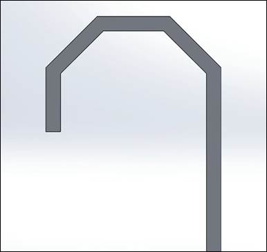
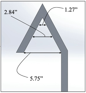

Figure 43 - Hook - Branch Compatibility
(a)
FINITE ELEMENT ANALYSIS
The team originally planned on using
a solid aluminum hook. After presenting this idea to our faculty advisor, we
were asked to consider a hollow hook instead. The concern with using a hollow
hook rather than solid was that it would not be able to withstand the expected
vibrations. To test this, the team used SolidWorks to model the hollow aluminum
hook, then ran a Finite Element Analysis on the hollow model. The results
showed that the hollow aluminum hook would be able to withstand the expected
vibrations (negligible deflection). This is advantageous over the solid
aluminum hook since it dramatically reduces weight. This led the team to move
forward with a hollow hook.

Figure
44 - FEA Simulation of Hollow Hook
TASK
7 - UPDATED SOLIDWORKS ASSEMBLY

Figure
45 - Hook Assembly Model (Version 2)
TASK
8 - MACHINING & ASSEMBLY
Once all the raw materials arrived,
the team began work in the machine shop manufacturing the following components.
o
Lower
Motor Mounts
o
Upper
Motor Mounts
o
Lower
Pillow Block Mount
o
Upper
Pillow Block Mount
o
Hook
Frame
o
Hook
Insert
o
Offset
Mass
o Shaft
o
Polycarbonate
Case
Aluminum 6061-T6 was the metal alloy
chosen to make the hook frame and its components (mounts) out of. 6061 Aluminum
is, by any measure, the most commonly used aluminum alloy in the world. It is
useful in almost any application due to its strength, heat treatability,
machinability, weldability, as well as high resistance to corrosion, stress,
& cracking. In our case, we needed an alloy that had a good strength-to-weight
ratio and was relatively easy to machine and weld.
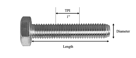
Bolt Sizes
Bolt Size: 3/8" - 16 x 2"
(Diameter) " - (TPI) x (Length)
"
When dealing with bolts, it is
important to know how bolt sizes are defined (U.S. Customary). Bolts are
defined by their diameter, threads per inch (TPI), and length. The first number
indicates the diameter of the bolt (in inches) while the second number indicates
the number of threads per inch measured along the length of the bolt. The third
number defines the length of the bolt. For the example above, the bolt is 3/8
inches in diameter, has 16 threads per inch, and a length of 2 inches.
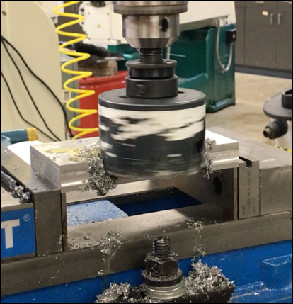
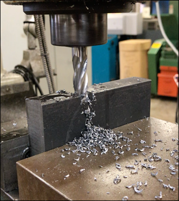
Lower
Motor Mounts
The lower motor mounts provide a
resting platform for the motor to be attached to the hook. First, 3"
diameter holes were cut using a circular cutter on the mill machine (allows
motor to fit on top). Then, a 3/8" hole was drilled through the length of
each mount. This through-all hole will allow a bolt and nut to secure the
mounts onto the hook frame. Next, 1" x 1.5" rectangular cuts were created
using endmills. These rectangular slots allow the mounts to be inserted onto
the base of the hook frame. Finally, 5/16" holes were drilled & tapped
(3/8"-16) onto both sides of each mount to allow the upper mounts to be
secured on top. Countersinks were done on each hole to deburr the rough edges.
|
Figure 46 - Cutting 3" Hole |
Figure 47 - Drilling 3/8" Hole |

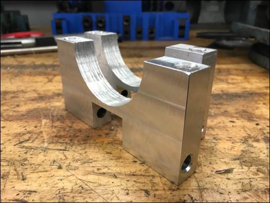
Figure
48 - Lower Motor Mounts
NOTE:
To View SolidWorks Part Drawing (Lower Motor Mount), Click HERE
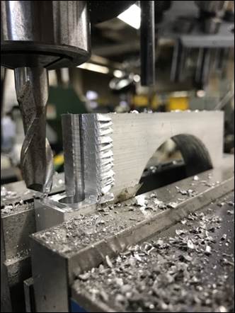
Upper
Motor Mounts
The purpose of the upper motor
mounts is to secure the DC Motor into place by attaching to the lower motor
mounts with bolts. The 3" circular hole was again done by using the
circular cutter on the mill. Then, 3/8" holes were drilled through the
center of each rectangular tab (with countersink). 3/8"-16 bolts will go
through these holes and connect to the lower motor mount. This will keep the
motor secured in place. After that, an endmill was used to create rectangular
tabs on each end of the mounts. Next, we adjusted the mill to a 45-degree angle
to create angled cuts. This was done to approximate the outer circular shape.
To get closer to the desired circular shape, we used the vertical belt sander. This
allowed us to carefully shape the outer curvature.
|
Figure 49 - Cutting Excess |
Figure 50 - Angled Cuts using Mill
(45 deg) |

Figure
51 - Using Belt Sander to Shape Outer Curvature
Figure
52 - Upper Motor Mounts
NOTE:
To View SolidWorks Part Drawing (Upper Motor Mount), Click HERE
Lower
Pillow Block Mount
The lower pillow block mount allows
the pillow block closest to the motor to be secured onto the hook frame.
Similar to the lower motor mounts, a 3/8" hole was drilled through the
long side of the mount. A 6.5" long 3/8" bolt will pass through this
hole and connect the mount to the hook frame (using Nylon Insert Lock Nut). Next,
27/64" holes were drilled and tapped (1/2"-13) on top of the mount.
These threaded holes allow the pillow block to be bolted onto the mount. Two
0.2010" (#7 drill size) holes were then drilled and tapped (1/4"-20)
onto both sides of the lower pillow block mount. The polycarbonate case that
surrounds the offset mass will be bolted onto these threaded holes (on lower
and upper pillow block mounts). Finally, a rectangular slot (1" x 1.5")
was cut out using an endmill. Again, this slot allows the mount to be inserted
onto the hook frame.
Figure
53 - Using Tap to Create Threads in Hole
|
Figure 54 - Drilling 0.2010"
Holes |
Figure 55 - Cutting Rectangular
Slot |

Figure
56 - Lower Pillow Block Mount
NOTE:
To View SolidWorks Part Drawing (Lower Pillow Block Mount), Click HERE
Upper
Pillow Block Mount
The upper pillow block mount attaches
near the vertex of the hook frame and provides a platform for the pillow block furthest
away from the motor to be secured onto. Considering this a relatively large
component, two 3/8" holes were drilled through the mount for attachment to
the hook (bolts and nuts). Again, two 27/64" holes were drilled and tapped
(1/2"-13) on top of the mount, used to bolt down the pillow block. Two
0.2010" (#7 drill size) holes were also drilled and tapped (1/4"-20)
onto both sides of the mount (used to secure polycarbonate case). This
particular mount features an incline that allows it to be flushed with the
tapered section of the hook frame. Similar to the upper motor mounts, the mill
was adjusted to 30-degrees
from the vertical to cut this incline gradually (using an endmill). Finally, a
large rectangular slot was cut out through the middle section to allow the hook
frame to fit in between.
|
Figure 57 - Cutting Incline |
Figure 58 - Preparing to Cut Slot |

Figure
59 - Trimming Slot Edges
NOTE:
To View SolidWorks Part Drawing (Upper Pillow Block Mount), Click HERE
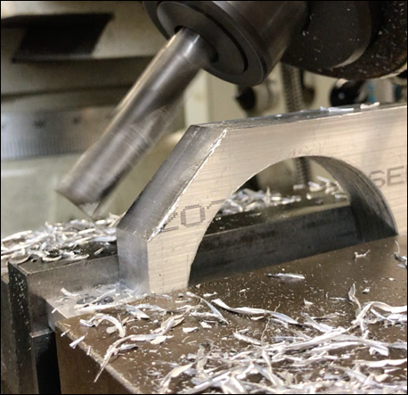
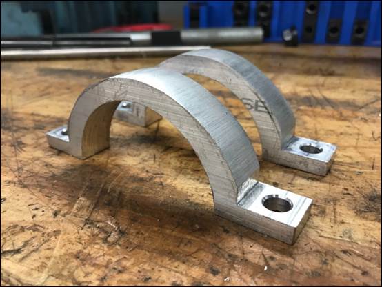
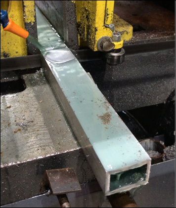
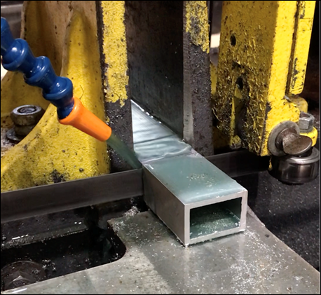
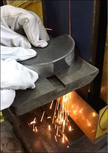
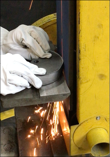
Hook
Frame
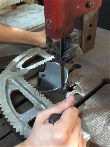
To create the hook, three hook frame
pieces were cut from one 3-foot-long rectangular aluminum tube (1" x 1.5")
using the horizontal bandsaw. These pieces were then trimmed to the appropriate
angle at each end (to connect with one another) using the vertical bandsaw.
After a careful sanding of the rough edges, the three pieces were tig welded
together. Since the hook is hollow, it was relatively easy to join the pieces
together. The Air angle die grinder was used to smooth out the welded joints. 3/8"
holes were then drilled through the hook at specific locations to allow the
mounts to be secured.
|
Figure 60 - Cutting Hook Piece 1 |
Figure 61 - Cutting Hook Piece 3
Excess |

Figure
62 - Hook Frame
Figure
63 - Drilling 3/8" Holes onto Hook Frame
NOTE:
To View SolidWorks Part Drawing (Hook Pieces 1-3), Click HERE
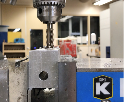
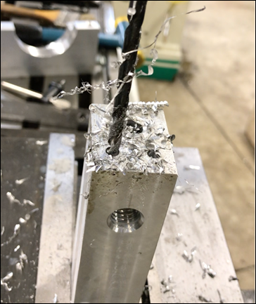
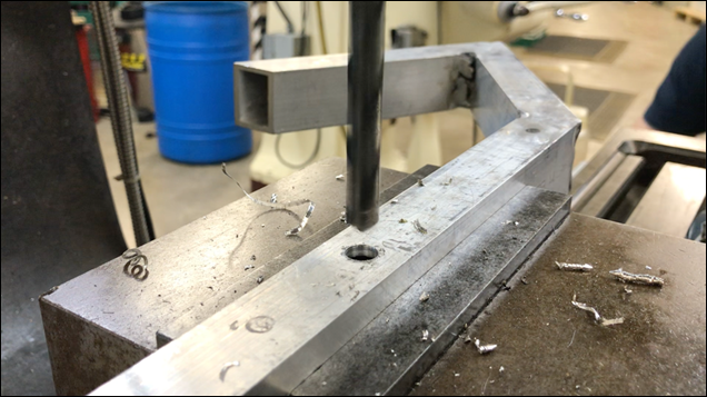
Hook
Insert
To connect the hook frame to the
pole, a hook insert was created. This hook insert began as a 1" x 1.5"
x 3" solid aluminum block. First, a 3/4" hole was drilled onto its
bottom side. This allows the pole tip to be attached. To fix this connection,
two roll pins were pressed through the hook insert and pole tip. Next, the other
side of the hook insert was machined to fit the inside of the hollow hook base.
Once the hook insert fit tightly into the hook frame, two 1/4" holes were
drilled through the hook frame and hook insert. These holes allow the hook
frame to be bolted onto the hook insert (detachable if desired).
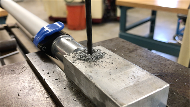
Figure 64 - Drilling Hole for Roll Pin
|
Figure 65 - Drilling 3/4"
Hole |
Figure 66 - Pressing Roll Pins |
Figure
67 - Hook Frame attached to Pole
NOTE:
To View SolidWorks Part Drawing (Hook Insert), Click HERE
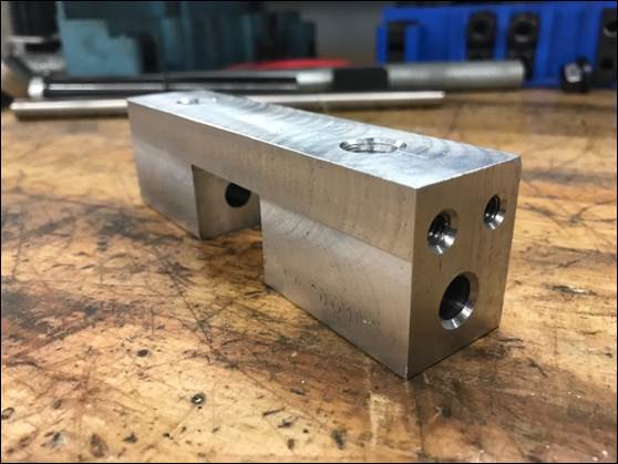
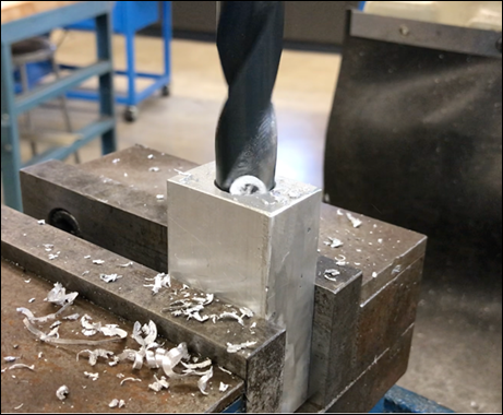
Offset
Mass
The
offset mass will be used to generate a force when spun by the motor (about the
shaft). In this case, A36 Carbon Steel was chosen due to its relatively high
density. This mild carbon steel grade contains chemical alloys that give it
properties such as ductility and strength, while being perfectly suitable for
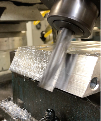
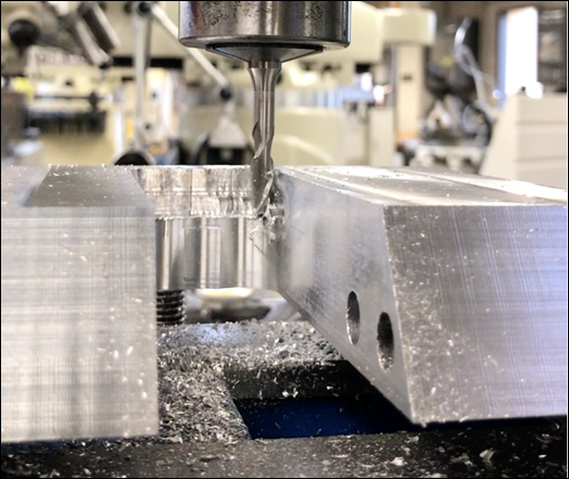
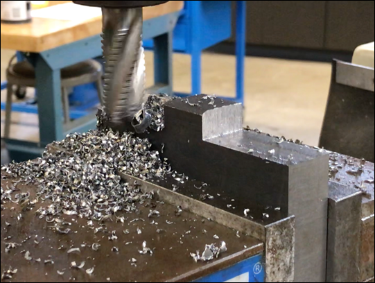
grinding, drilling, tapping, and machining processes. To start off, a 4-flute
endmill was used to cut off excess on each side of the steel block to create a
rectangular tab in the center. This tab will be used to drill the hole on which
the shaft will be inserted through. Next, a 1/2" hole was drilled into the
center of this rectangular tab (shaft insert). Initially we tried to use the
circular cutter to cut out the circular shape. However, since steel is much
stronger than aluminum, this method was ineffective in cutting through.
Instead, we used the vertical bandsaw to trim the outer curvature as close as
possible, after which we used the belt sander to smooth out the edges.
|
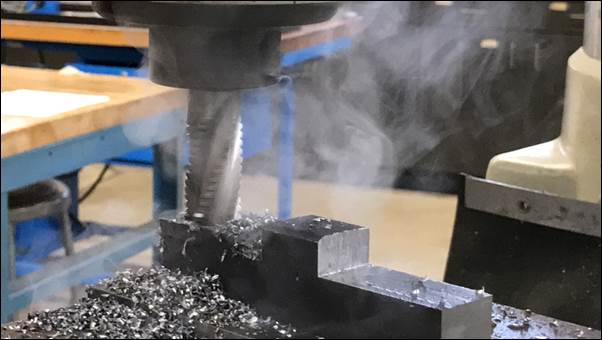
Figure 68 - Cutting Excess (4-Flute) |
Figure 69 - Cutting Excess
(Roughing Endmill) |
Figure
70 - Ben (Left) & Paul (Right) Milling Offset Mass
Figure
71 - Milling Offset Mass with Roughing Endmill (Adding Coolant)

Figure
72 - Ben (Left) & Miguel (Right) Milling Offset Mass
|
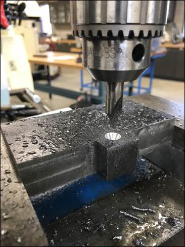
Figure 73 - Drilling 1/2"
Hole |
Figure 74 - Trimming Outer
Curvature |
|
|
|
|
Figures 75 & 76 - Using Belt
Sander to Round Offset Mass Edges |
|
To investigate the effects of
lighter offset masses on the generated force, thinner offset masses were
machined (same shape). With the original offset mass being 1 inch thick, the
other two masses machined are 0.75 inches thick and 0.5 inches thick. These
masses are interchangeable within the device. Since the generated force is
directly proportional to the square of the driving frequency, we want to find
out if a lighter mass spun at a higher frequency can generate a similar force
to that of a larger mass spun at a lower frequency.
NOTE:
To View SolidWorks Part Drawing (Offset Masses), Click HERE
Shaft
The shaft that will drive the offset
mass was cut to the appropriate length using the horizontal bandsaw. The shaft
is made of Steel and is 0.5" in diameter. In this case, the shaft will
connect to the motor via a spider coupling and guided through pillow blocks.
The offset mass will then be mounted through the shaft, between the two pillow
blocks. Two shaft collars will hold the offset mass in place. To transmit the
torque from the motor to the offset mass, a 0.2010" hole was drilled and
tapped (1/4"-20) through the bottom end of the offset mass, through the
shaft, and onto the other side of the offset mass. This allows a set bolt to
connect the offset mass to the shaft and transmit the torque. This method was
carried out on each one of the offset masses. Although the team originally wanted
to implement a key and slot joint to transmit the torque, the machine shop did
not have a broach size that would work with the offset mass.
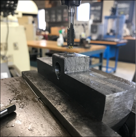
Figure
77 - Tapping Offset Mass
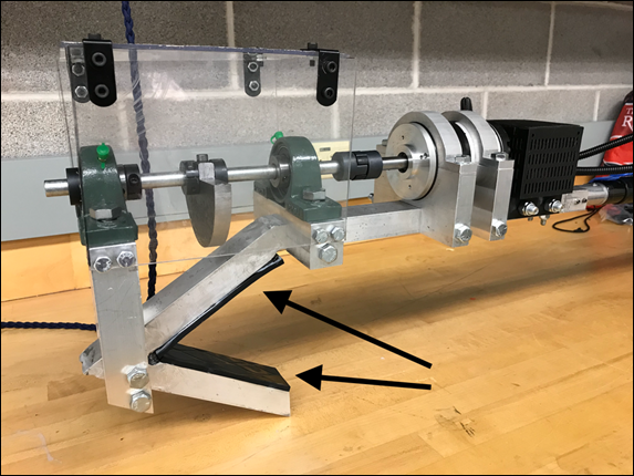
Polycarbonate
Case
A polycarbonate case was put
together to prevent any type of personal injury from the offset mass and/or interference
from protruding twigs and branches. This case is made from three clear, impact-resistant
polycarbonate panels, joined together with L-brackets. The polycarbonate panels
were cut to scale using the vertical bandsaw. The case was then placed around
the offset mass, being bolted into the sides of the lower and upper pillow
block mounts. Again, this case ensures no one is harmed during operation
(spinning offset mass) as well as protects the offset mass from hitting any
twigs or small branches when up on a tree.
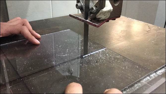
Figure
78 - Cutting Polycarbonate Panel using Vertical Bandsaw
NOTE:
To View SolidWorks Part Drawing (Polycarbonate Panels), Click HERE
Assembly
Once all the components had been
machined, the team was able to assemble the device. Although some parts were a
tighter fit than others, we were able to piece together each component. In this
case, we used nylon insert lock nuts to secure each mount onto the hook. Since
the assembly will undergo heavy vibrations during operation, we want to make
sure nothing comes loose. Nylon nuts are a type of locking nut that resist
loosening caused by vibration and normal use. Unlike free spinning nuts, nylon lock
nuts make use of a deforming elastic to stay in position against torque and
shock.
During assembly, it is important to
make sure the pillow blocks are aligned correctly. This allows the shaft to be
inserted smoothly and straight. In any case, the spider coupling (connects
motor output shaft to extended shaft) is designed to accept shaft misalignment and
help protect components from damage by damping shock and vibrations. Also, shaft
collars are positioned on each side of the pillow block furthest away from the
motor to prevent the shaft from translating in or out. Finally, each set
screw/bolt on the assembly (coupling, shaft collars, pillow blocks) must be
screwed onto the shaft. This helps prevent the coupling from detaching as well
as the offset mass from coming loose and sliding to one side.
Overall, the assembly process is
relatively simple and easy to follow. Each component is removable and can be
taken off if needed. Tools required for assembly include an adjustable wrench
(and/or ratchet), vice grips, and allen keys (different sizes).
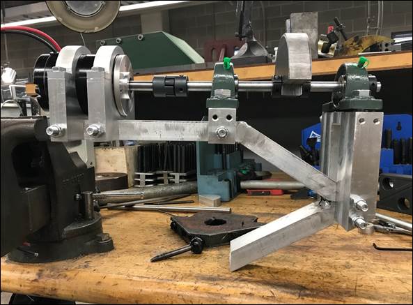
Figure
79 - Assembled Hook without Case (Front View)
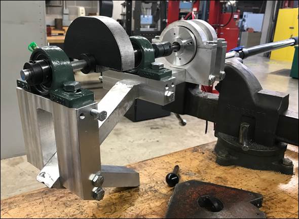
Figure
80 - Assembled Hook without Case

Figure
81 - Assembled Hook with Case (Front View)
CHECK OUT our Machining Process. See Video
Below!
TASK
9 - ELECTRONICS & 3D PRINTING
After assembling all the mechanical
components of the hook device, the team shifted its focus towards the
electronics. The motor will receive its power from two 12V batteries. These
batteries will need to be mounted on the hook and near the motor. To solve
this, the team designed a battery case that will house both batteries and be
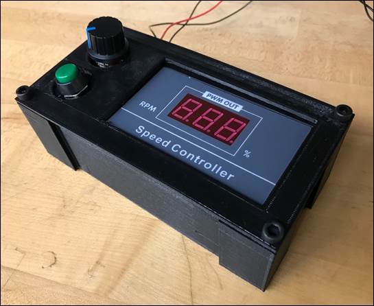
mounted directly behind the motor. In addition, to control the speed of the
motor, a speed controller will be used. The speed controller connects to both
the batteries and the motor and controls the voltage sent to the motor via a
potentiometer (knob). The speed controller must be easy to use and not have
wires exposed. The team therefore decided to design a case for the speed
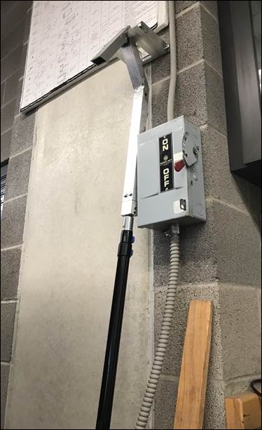
controller that will house the speed controller along with the ON/OFF button
and potentiometer. A cover lid was also designed to secure the speed controller
in place. The lid has openings that allow access to the ON/OFF button and the
potentiometer, as well as an opening to see the display (% Power). The speed
controller will be mounted on the pole to allow the user access to the
controls.
Battery Case
The battery case has two slots for
the pair of batteries to be inserted. The four walls surrounding the batteries
have multiple openings to allow for heat to be dissipated during use. The case
has two circular openings on the back side of the case to allow the battery
wires to go through and connect to the speed controller. The case also has two
side panels on its bottom side that allow it to sit on top of the hook frame. Each
of these panels has two 3/8" holes that serve to secure the case to the
hook frame (using bolts and nuts). A removable lid was also designed to close the
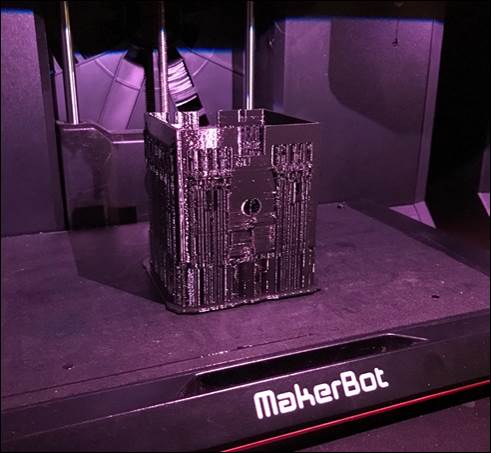
case and prevent the batteries from slipping out during operation. Both the
battery case and lid were designed on SolidWorks and 3D printed using the
MakerBot Replicator +.
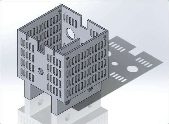
Figure
82 - Battery Case on SolidWorks
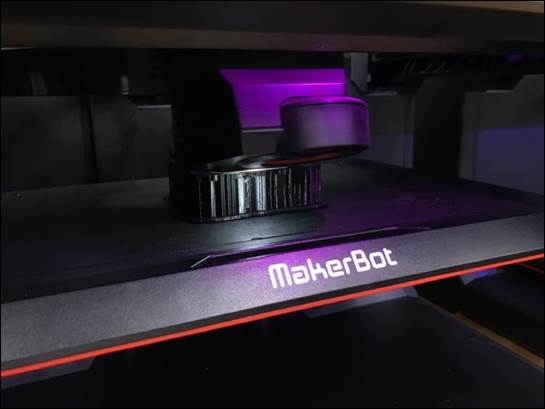
Figure
83 - 3D printing Battery Case
Figure
84 - Battery Case with Supports (Excess)
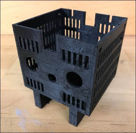
Figure
85 - Battery Case (Excess Removed)
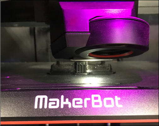
Figure
86 - 3D printing Battery Case Lid
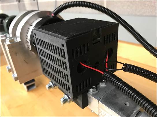
Figure
87 - Battery Case on Hook
Speed
Controller Case
The speed controller case is a
rectangular box that has supports for the speed controller to sit on top of as
well as two hollow cylinders extruded from the base that house the ON/OFF
button and potentiometer. On the back side there is a rectangular slot that
allows the wires from the motor/batteries to enter the case and connect to the
speed controller. On each corner, there are holes for the lid to be screwed on.
Again, the cover lid has two holes that allow access to the button and
potentiometer as well as a rectangular opening for the speed controller
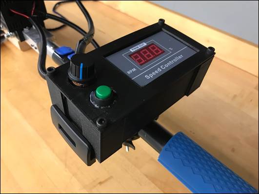
display. The speed controller case will be mounted to the pole using an
adjustable clamp mount. Both the speed controller case and cover lid were
designed on SolidWorks and 3D printed using the MakerBot Replicator +.
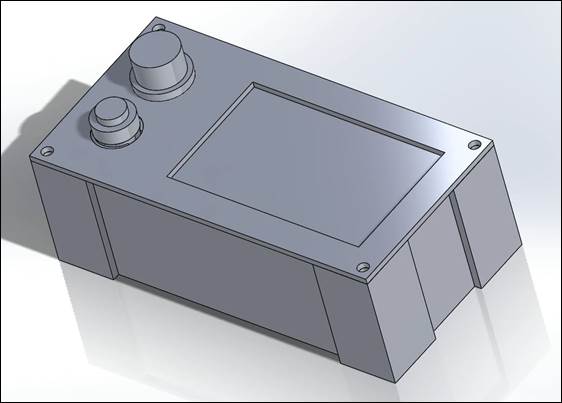
Figure
88 - Speed Controller Case & Lid on SolidWorks
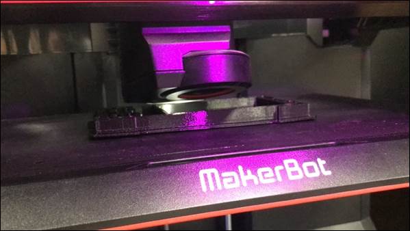
Figure
89 - 3D Printing Speed Controller Case
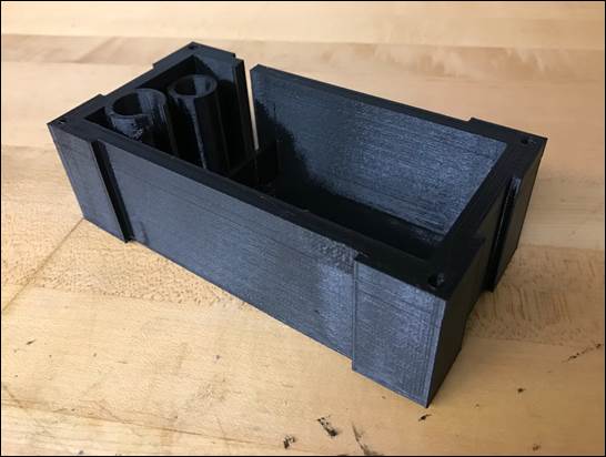
Figure
90 - Speed Controller Case
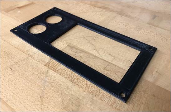
Figure
91 - Speed Controller Case Lid
Figure
92 - Speed Controller Inside Case
Figure
93 - Speed Controller Case Mounted
TASK
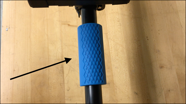
10 - OTHER ATTACHMENTS
To attach the speed controller case
to the pole, an adjustable clamp mount (meant for tablets) was purchased. This
mount will hold the case in place while being clamped to the pole. This way,
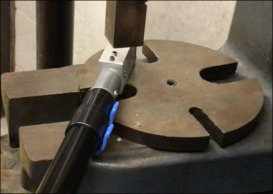
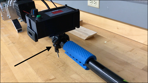
the user can always control the device. Rubber pads were also glued (super
glue) to the tapered section of the hook to improve the grip on the branch. A
grill pattern design (tread) was pressed onto the rubber pads using the
hydraulic press. This will enhance the grip of the rubber pads. In addition,
rubber pole grips were added to the pole. Although the pole came with pole
grips, they were made from foam and did not provide sufficient grip when
handling. These new grips give the user a much firmer grip when maneuvering the
device. Also, wire tubing was added to the battery and motor wires. This was
done to provide abrasion resistance and environmental protection. Together,
these attachments provide a better user-experience while improving the
performance of the device.
Figure
94 - Adjustable Clamp Mount (Speed Controller)
Figure
95 - Rubber Pad Attachments
Figure
96 - Rubber Pole Grips
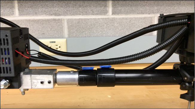
Figure 97 - Wire Tubing
CHECK OUT our 3D Printing Process. See
Video Below!
Design for X (DFX)
DFX stands for Design For [Variable]
"X", where X's are not mutually exclusive since there are always tradeoffs.
X can include things such as- Function, Usability, Safety, Manufacture, Assembly,
Reliability, Maintainability, Environment, Appearance, & Variety.
Design For Assembly (DFA):
Design of the components that consider how the assembly will be performed to
ensure that the costs are optimized (minimized).
1st -
Electronic components were minimized by using a simple analog circuit and motor
with no Arduino or computer to control the speed. Only necessary parts were
included in the mechanical components.
2nd -
No parts were joined in the final assembly unless it was necessary for the
parts to be connected during use. Only simple joints (bolts, screws) were used
in the assembly.
3rd -
The device can be disassembled and taken apart, replacing the individual
components with another similar component. This was achieved by using easy to
manufacture parts with standard components like nuts, bolts, screws, and
electronics. This makes it easy and convenient to replace any broken or damaged
parts with another similar component.
4th -
The assembly or the device is a simple process that requires several common
tools.
5th -
In the assembly process, the main hook is used as a reference for locating the
positions of the remaining components.
6th -
The speed controller case was designed in SolidWorks using "top-down"
assembly. This made it convenient to ensure that the body and the lid were
compatible by referring to each other in the assembly file.
7th -
Due to the nature of the device, being required to reach tall branches, the
center of gravity is somewhat high. However, several options for lowering
center of gravity are being discussed to make the part easier to maneuver.
8th
- Currently, most of the weight is concentrated near the top of the device.
This poses some stability issues due to the center of gravity being offset.
9th
- The design of the hook is a bit heavy but is durable to carry by one person.
The weight of the hook is about 20 lbs. or so.
10th
- The polycarbonate wall is to prevent any safety hazards like someone sticking
their fingers inside while the offset mass is at operations, when in operation
no branches or twigs can tied around the offset mass while in use.
11th
- No shimming is necessary in the assembly of the device. Appropriate
tolerances of +/- 0.005" allow the parts to fit snugly in their specified
position. It also eliminates the presence of any gaps, making any shimming
unnecessary.
12th
- Most of the device's joints are left exposed for easy access to the
fasteners. In the case that components are covered by the polycarbonate case,
the casing is clear, which still allows the user to easily see inside. The
polycarbonate casing can be easily removed to allow access to the inner
components if any adjustment is needed.
13th
- All mechanical fasteners (nuts/bolts) are standardized products that can be
easily purchased in bulk from suppliers.
14th
- The entire hook assembly is symmetric (left/right). All the manufactured
components (mounts, offset masses) are symmetrical about one axis (at least).
15th
- The proper location of all components is easy to determine. Components will
not be able to be fastened in the wrong position.
16th
- The device is designed so that it can be easily adjustable. However, if the
device is adjusted to the user's liking, it will not need to be regularly re-adjusted
to maintain its position. Nylon nuts are used to ensure that the fasteners do
not easily loosen during normal vibration of the device.
17th
- Wire tubing is added to the wires connecting the speed controller to the batteries
and motor. This not only keeps them from tangling but also prevents the wires
from getting damaged due to the outdoor elements.
18th
- The hollow aluminum tubing and solid aluminum bars used in the manufacture of
the components are sufficiently sturdy, providing a robust device that can
withstand its expected loads.
19th -
The upper pillow block mount has a chamfer that aligns with the angle of the
hook. The rectangular shapes cut away from the lower pillow block mount and
lower motor mounts ensure that they will be symmetrical with the hook.
20th
- In creating the engineering drawings, proper notation was used and thorough
information easily communicated the design intentions to the manufacturer. A
user manual detailing assembly of the device is in progress.
21st
- When designing the mechanical components to the hook, threading, drilling,
etc. were used during the time in the machine. After completing each component,
most of them had burr inside the trilling. Therefore, they had to be removed
for the components to fit inside properly.
Design For Manufacture (DFM): The design is considered with
regards to the process of manufacturing it and lowering the costs needed for
it.
1st -
Using a taper hook instead of an adjustable one along with having pure analog
components for the electronics simplifies the design of the hook assembly. The
blocky metal pieces are secured using simple nuts and bolts.
2nd -
When designing the device, the equipment available to us and their capabilities
were considered. Only parts that could be manufactured in the machine shop were
designed. This equipment includes milling machine, lathe, tig welder, and belt
sander.
3rd
- Aluminum was selected for its light weight and decent strength; good strength-to-weight
ratio and is affordable.
4th
- The main hook assembly frame maintains a constant cross-sectional area; stress concentrations are not a
considerable risk as the aluminum frame has uniform wall thickness.
5th
- First use the horizontal bandsaw to cut an estimate for the outer edge
dimensions of the rectangular pieces (both for the metal and polycarbonate
materials). Mill all the metal blocks to its border size (rectangular prisms),
then mill out all the corners and right angles of the block pieces. Drill all
the holes of all the pieces with the smallest diameter specified in the
blueprints, then all the holes with the next biggest diameter, and so on [until
all holes of all sizes are drilled]. Apply the same practice with the holes
that require threading (use tap drills and taps). Finally, angle the Mill
machine to manufacture the slanted geometries of the appropriate metal pieces.
Other pieces with curved geometries were first subject to the vertical bandsaw
and then the belt sander.
6th
- For the mill, we tried to stay on the same constant number (zeroing out each
time) when we drilled holes to each block piece.
7th
- A tolerance of +/- 0.005 inches was chosen to maintain adequate design while
not spending too much time on minute details.
8th
- To minimize weight of the device, hollow aluminum tubing was chosen, rather
than solid pieces. To ensure a wall thickness of 0.125" was sufficient to
withstand its expected loads, finite element analysis was performed.
9th
- Standardized nuts and bolts were utilized in the assembly of the device. This
allows parts to be easily replaceable without needing any special tooling.
Also, standard endmills were used when machining the aluminum and steel
components (two-flute & four-flute). These are regularly-used endmills when
working with a mill machine.
10th
- The battery case holder and the speed controller casing were made from a 3-D
printer (MakerBot). These items were placed on the hook at the appropriate
point to operate the offset mass.
11th
- The milling machine was utilized for almost all parts of the assembly
including cutting, drilling, and tapping. This prevents the manufacturer from
needing to jump from machine to machine frequently. In addition, the speed
controller case was used to house the digital display as well as the
potentiometer and power button.
12th
- The critical characteristics involve tight tolerances (0.005") in the
placement of the upper pillow block mount. Aluminum 6061-T6 is also corrosion
resistant.
13th
- The presence of a milling machine monitor was essential in allowing for the
necessary tolerance for the upper pillow block mount. Without this piece of
equipment, it would be extremely difficult to create this piece to
specification.
14th
- The cost of the components was minimized by using the same nuts and bolts
whenever possible. This minimizes the number of required components while
keeping costs low. The amount of aluminum stock necessary was estimated by
referring to the CAD model. This resulted in very little scrap metal after
manufacturing.
15th
- Many of the more crucial tolerances had a range of +/- 0.005 inches. These tolerances were for drill hole
sizes, tap drill sizes, tap sizes, hole locations from the edges, and parts
that are in tight contact with other pieces.
16th
- Before deciding how to machine the parts, the typical tolerances for the
milling machine were determined. It was found that tolerances of +/- 0.005"
are typical and feasible for manufacture using the milling machine.
17th
- The parts that can easily be inspected are removing the polycarbonate wall by
disassembling it and disassembling the offset masses.
18th
- Secondary processes were only used when necessary (upper motor mounts). Most
components were completed on the milling machine.
19th
- Rather than repositioning the piece, the milling machine angle was adjusted
when possible.
20th
- Standardized endmills, drill sizes, and taps were used in nearly all pieces.
This minimizes the need to use special techniques or tools to create non-standard
features.
21st
- Though no fillets were done on any component, rounded curvatures were done on
the upper motor mounts and the offset masses (using the mill at angle/vertical
bandsaw/belt sander).
22nd
- Using the mill machine leads to most parts manufactured having general block-like
shapes [with corners/right angles], but it is easy to manufacture and beginner-friendly.
23rd
- No special processes were performed.
24th
- All components were designed on solid works, after which a drawing was
created for each. These drawings contain the material, tolerance, and
appropriate dimensions from each side (front, side, top). The component
drawings are easy to follow and require no additional calculations from the
person machining.
Quality Function Deployment (QFD)
Quality Function Deployment (QFD) is a mechanism to ensure
that the customer needs drive the entire product design and production process,
including product design and engineering, process development and prototype
evaluation, as well as production, sales, and service.
Table 4 - QFD Exercise
|
Customer
Quality Experience |
Design
Spec. |
Critical
Functions |
Components |
|
Lightweight |
Primary
material is aluminum. Hollow tubing used when possible. |
Reduces
weight that customer has to lift/maneuver |
Hollow
Hook (Aluminum Tubing) |
|
Ease
of Use |
Handle
Grips |
Enhanced
Grip |
Extender
Pole |
|
Relatively
Simple Assembly |
Assembly
Time: < 10 minutes |
Minimal
Tool Inventory |
Vibration-Resistant
Nuts. Standardized nuts/bolts |
Failure Mode & Effects Analysis
(FMEA)
FMEA is a step-by-step approach to
identify all the possible failure modes in a design, a manufacturing or
assembly process, or a product/service, along with its consequences (effect
analysis). Failure mode are the ways, or modes, where something will fail.
Failure modes are errors/defects that can affect the customer and either actual
or potential. Effects analysis refers to the studying the consequences
of those failures.
The objective of FMEA is to avoid
risk by: Identifying and quantifying the ways in which a product may fail, examining
the effects that failure has on the stakeholders, determining the cause of each
failure, listing the methods of detecting potential failures prior to
production, as well as identifying and implementing corrective actions. There
are four main failure types: Usability, Manufacturability, Service and
Maintenance, & Internal Functioning.
Table 5 - FMEA Chart
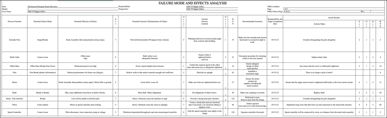
Click
HERE
to View FMEA Chart.
Bill of Materials
|
Part Name |
Description |
Image |
Material |
Justification |
MFG Process |
Justification |
Qty |
Cost/Unit |
Total |
Source |
|
Hook Frame |
Latches onto branch. |
|
Al |
Strong, Lightweight, Easy to
Machine. |
Milling, Tig Welding, Sanding |
Drilling involved. Hollow Aluminum
Tubes are relatively easy to weld together. |
1 |
$16.01 |
$16.01 |
|
|
Lower Motor Mount |
Hold Motor in place from below,
ensuring shaft lines up with pillow blocks. |
|
Al |
Strong, Lightweight, Easy to
Machine. |
Milling |
Facing, Cutting, Drilling &
Tapping. |
2 |
$10.08 |
$20.16 |
|
|
Upper Motor Mount |
Hold motor in place from above. |
|
Al |
Strong, Lightweight, Easy to
Machine. |
Milling & Sanding |
Facing, Cutting & Drilling. |
2 |
$6.73 |
$13.46 |
|
|
Lower Pillow Block Mount |
Allows lower pillow block to mount
to main hook frame. |
|
Al |
Strong, Lightweight, Easy to
Machine. |
Milling |
Facing, Cutting, Drilling &
Tapping. |
1 |
$12.07 |
$12.07 |
(Custom Cut) |
|
Upper Pillow Block Mount |
Allows upper pillow block to mount
two main hook frame. |
|
Al |
Strong, Lightweight, Easy to
Machine. |
Milling |
Facing, Cutting, Drilling &
Tapping. |
1 |
$39.53 |
$39.53 |
(Custom Cut) |
|
Large Offset Mass |
Used as rotating unbalance. Will
generate vibration when spun. |
|
A36 Carbon Steel |
Strong, Dense, Relatively Easy to
Machine. |
Milling & Metal Cutting
(Vertical Bandsaw) |
Difficult to cut circular shape. |
1 |
$12.32 |
$12.32 |
(Custom Cut) |
|
Medium Offset Mass |
Used as rotating unbalance. Will
generate vibration when spun. |
|
A36 Carbon Steel |
Strong, Dense, Relatively Easy to
Machine. |
Milling & Metal Cutting
(Vertical Bandsaw) |
Difficult to cut circular shape. |
1 |
$9.13 |
$9.13 |
(Custom Cut) |
|
Small Offset Mass |
Used as rotating unbalance. Will
generate vibration when spun. |
|
A36 Carbon Steel |
Strong, Dense, Relatively Easy to
Machine. |
Milling & Metal Cutting
(Vertical Bandsaw) |
Difficult to cut circular shape. |
1 |
$7.31 |
$7.31 |
(Custom Cut) |
|
Hook Connector |
Connects hook to pole. |
|
Al |
Strong, Lightweight, Easy to
Machine. |
Milling |
Facing, Cutting, Drilling, &
Tapping. |
1 |
$22.19 |
$22.19 |
|
|
Filling |
Provides extra support to the pole
interface. |
|
Al |
Strong, Lightweight, Easy to
Machine. |
Turning |
Cylindrical piece is best machined
using Lathe. |
1 |
N/A |
N/A |
Given from Machine
Shop |
|
DC Motor |
Generates rotational motion. |
|
Al |
Lightweight, Robust. |
N/A |
N/A |
1 |
$79.00 |
$79.00 |
|
|
1/2" to 1/2" Rubber
Spider Coupling |
Connects motor shaft to steel
shaft. Corrects for any misalignment of the shaft. |
|
N/A |
N/A |
N/A |
N/A |
1 |
$7.00 |
$7.00 |
|
|
1/2" Shaft |
Transmits torque. Extends motor
shaft. |
|
Steel |
Strong, Stiff, Corrosion
Resistant. |
Hot Rolling |
N/A |
1 |
$15.85 |
$15.85 |
|
|
Pillow Block |
Protects motor from heavy
vibrations. Supports rotating unbalance. |
|
Cast Iron & Chrome Steel |
N/A |
N/A |
N/A |
2 |
$7.88 |
$15.75 |
|
|
1/2" Bore Shaft Collars |
Secures rotating components in
place. |
|
Carbon Steel |
N/A |
N/A |
N/A |
4 |
$2.75 |
$10.99 |
|
|
Polycarbonate Case |
Protect user from rotating offset
mass. Also protects mass from interfering with protruding branches. |
|
Polycarbonate |
Impact Resistant, Hard. |
N/A |
N/A |
1 |
$16.00 |
$16.00 |
|
|
L-Brackets |
Piece together polycarbonate
panels. |
|
Steel |
N/A |
N/A |
N/A |
1 |
$6.99 |
$6.99 |
|
|
Rubber Strip |
Better grip when being placed onto
the Mesquite branch. Purposed to increase the grip between the hook surface
and the tree branch. |
|
Neoprene Rubber |
High Coefficient of Friction,
Resilient. |
N/A |
N/A |
1 |
$6.93 |
$6.93 |
|
|
Flag Pole |
Allows the user to grab onto the
assembly. |
|
Stainless Steel |
Strong, Stiff. |
N/A |
N/A |
1 |
$22.99 |
$22.99 |
|
|
12V Battery Packs & Fast
Charger |
Supply power to motor. |
|
N/A |
N/A |
N/A |
N/A |
1 |
$64.97 |
$64.97 |
NOTE: Link Above is Bundle
(Charger and One Battery Pack) Another Battery Pack was Purchased
Separately (Price is Included) |
|
Battery Case & Lid |
House the 12 Volt batteries and
mount on hook frame. |
|
PLA |
Lightweight, Cheap, Sustainable. |
3D Printing |
Fast, Easy, Relatively Cheap. |
1 |
N/A |
N/A |
MakerBot Replicator + (MakerSpace) |
|
Speed Controller Case & Lid |
Houses speed controller components
(display, button, potentiometer). |
|
PLA |
Lightweight, Cheap, Sustainable. |
3D Printing |
Fast, Easy, Relatively Cheap. |
1 |
N/A |
N/A |
MakerBot Replicator + (MakerSpace) |
|
Speed Controller |
Allows user to control rotational
speed. |
|
N/A |
N/A |
N/A |
N/A |
1 |
$11.09 |
$11.09 |
|
|
3/8"-16 Tap Bolt, 6 1/2 in.
Length |
Secure pillow blocks and motor
mounts onto hook. |
|
Grade 5 Steel |
Hard & Strong |
N/A |
N/A |
5 |
$1.43 |
$7.13 |
https://www.grainger.com/product/FABORY-3-8-16-22TC18?searchQuery=22TC18&searchBar=true |
|
3/8"-16 Hex Head Cap Screw, 1
in. Length |
Secure top motor mounts onto
bottom motor mounts. |
|
Grade 5 Steel |
Hard & Strong |
N/A |
N/A |
4 |
$0.51 |
$2.02 |
https://www.grainger.com/product/FABORY-3-8-16-41UC06?searchQuery=41UC06&searchBar=true |
|
3/8"-16 Hex Head Cap Screw, 3
in. Length |
Secure battery case to hook frame. |
|
Grade 5 Steel |
Hard & Strong |
N/A |
N/A |
2 |
$0.72 |
$1.43 |
https://www.grainger.com/product/GRAINGER-APPROVED-3-8-16-2CA14 |
|
1/2"-13 Hex Head Cap Screw, 1
1/4 in. Length |
Secures pillow blocks onto pillow
block mounts. |
|
Grade 5 Steel |
Hard & Strong |
N/A |
N/A |
4 |
$0.44 |
$1.75 |
https://www.grainger.com/product/FABORY-1-2-13-22TC38?searchQuery=22TC38&searchBar=true |
|
1/4"-20 Hex Head Cap Screw,
3/4 in. Length |
Secure polycarbonate case on sides
of pillow block mounts. |
|
Grade 5 Steel |
Hard & Strong |
N/A |
N/A |
8 |
$0.10 |
$0.80 |
https://www.grainger.com/product/FABORY-1-4-20-2CA50?searchQuery=2CA50&searchBar=tr+ue |
|
1/4"-20 Hex Head Cap Screw, 1
5/8 in. Length |
Secure pole to hook connector and
hook connector to hook frame. |
|
Grade 5 Steel |
Hard & Strong |
N/A |
N/A |
4 |
$0.18 |
$0.70 |
https://www.grainger.com/product/FABORY-1-4-20-22TA77?searchQuery=22TA77&searchBar=true |
|
3/8"-16 Nylon Insert Lock Nut |
Used in conjunction with bolts to
secure parts in place. Nylon nuts reduce likelihood that parts will come
loose from vibrations |
|
Grade 5 Steel |
Hard & Strong |
N/A |
N/A |
5 |
$0.11 |
$0.57 |
|
|
1/4"-20 Nylon Insert Lock Nut |
Used as above nylon nuts with
different sized bolts. Prevents loosening from vibrations while securing
parts in place |
|
Grade 2 Steel |
Hard & Strong |
N/A |
N/A |
4 |
$0.06 |
$0.22 |
|
|
TOTAL |
- |
- |
- |
- |
- |
- |
- |
- |
$424.36 |
- |

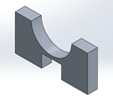
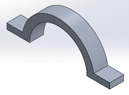
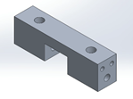
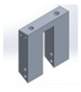

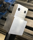
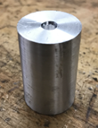

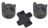
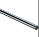
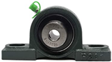
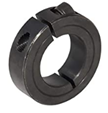
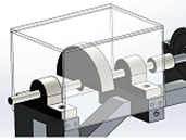
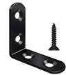
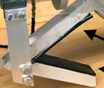
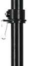

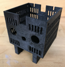


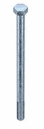

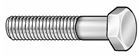
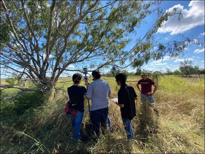
Figure 98 - Team Attaching Hook to Mesquite
Branch
The objective of the Testing &
Validation stage is to examine the performance of the product and determine how
well the design works.
Relating
to our product, the team established two main objectives we intend to
accomplish during this stage.
1. Identify problem areas in the
embodiment design by operating the device under certain conditions and taking
note of the results.
2. Determine ranges of controllable
parameters (such as frequency, voltage, and mass) that will optimize the
effectiveness of the device.
For our testing phase, the team
revisited the ranch and operated the device running several experiments. Below are
several tests. By analyzing the results of each test individually, the team can
identify the optimum strategy for operating the machine, thus maximizing
harvesting efficiency.
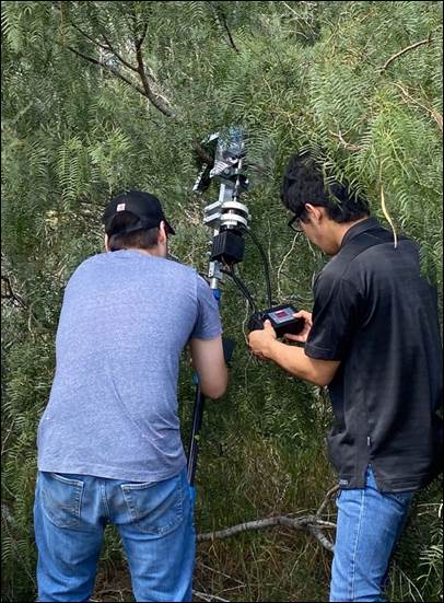
Figure
99 - Ben (Left) & Paul (Right) Operating Hook
TEST
1 - Voltage vs Frequency
10/5/2021, Miguel
Martinez, Paul Silva, Benjamin Huerta, Joshua Sanchez
Purpose: This test serves to characterize
the operation of this device by mapping out frequencies at specific voltages.
This allows the user of the device to accurately specify what frequency they
want to operate the device at, then use the speed controller to set the motor
to that frequency. In the case that the user wants to operate the device at the
natural frequency of the beans/branches, they will be able to do so.
Tools Required
o Adjustable
Wrench
o Allen
Wrench
o Tachometer
o Reflective
Tape
Procedure
o For
this assembly, only one 12 V battery is placed and used for this setup.
o There
will be three masses that will be interchanged from the large mass, medium
mass, and small mass for the first, second, and third parts, respectively.
o The
hook assembly is connected to the heaviest offset mass and the polycarbonate
case is attached around it for the first part.
o The
wires of the motor should be attached to the battery (which also has wiring
connected to the ON/OFF button and the speed controller).
o Before
connecting the motor to the battery, however, first take the hook assembly and
orient it vertically.
o Take
a piece of reflective tape and attach it to the coupler
o Take
out the tachometer and have it ready to shine the laser at a point where the
reflective tape will go back to when the motor spins the coupler.
o Have
the speed dial preset to 0.0% power.
o Before
connecting the circuit, be sure to establish a firm grasp on the pole and shaft
in anticipation for the vibrations (do this before each run). Having two people is recommended for a
stable grasp on the assembly.
o Attach
the wiring for the battery to the motor.
o Increase
the percentage power of the speed dial until the shaft and unbalanced mass
starts to move.
o Shine
the tachometer towards the area where the reflective tape spins for at least 10
seconds.
o Lower
the power percentage back to 0.0% to record the speed measurement from the
tachometer. This is Run 1.
o If
desired, you can take several measurements of the rotational speed at the same
percentage of power and then average them out.
o Record
the percent power and the rotational speed on a table.
o For
the next several runs in succession, increase the percent power from the speed
controller by 5 percent each time.
o Repeat
this process until you get the speed measurements of the final run at 50.0%
power for a single 12 V battery.
o Moving
on to the second part, clamp the assembly horizontally to a table and carefully
use a standard adjustable wrench to remove the screws that are attaching the
polycarbonate case to the assembly.
o Remove
the casing.
o Remove
the screws that are securing the upper pillow block mount.
o Slide
the upper pillow block mount out of the shaft.
o Unscrew
the key going through the mass and shaft.
o Use
an Allen wrench to untighten the clamps in front of and behind the heavy offset
mass.
o Slide
the heavy offset mass and clamps off the shaft.
o Slide
the clamps and the medium offset mass onto the shaft.
o Use
the Allen wrench to tighten the clamps around the medium mass.
o Re-insert
the upper pillow block mount on the shaft and tighten its corresponding screws
to keep it in place.
o Re-insert
the [polycarbonate] casing around the medium offset mass and tighten the
attaching screws again.
o Proceed
to follow the steps associated with running the test to measure the percent
power vs the speed (in RPM) measured by the tachometer.
o This
time, continue the runs in the same fashion (increasing by 5.0% each time) to
55.0 percent power for the final run.
o Be
sure all your measurements are documented with each run.
o Change
the mass out, once done performing the runs for the second part, to the small
offset mass using the same procedure described earlier (for removing and
changing the masses to the shaft).
o For
this third part, perform the runs in the same fashion, this time going up to a
final run using 70.0% power.
Table 6 - Voltage v. Frequency (Large Offset Mass)
|
Percent Power (%) |
Rotational Speed (RPM) |
|
20 |
115 |
|
25 |
168.4 |
|
30 |
237 |
|
35 |
334.6 |
|
40 |
359.7 |
|
45 |
442.2 |
|
50 |
495.2 |
Table 7 - Voltage v. Frequency (Medium Offset Mass)
|
Percent Power
(%) |
Rotational
Speed (RPM) |
|
20 |
148.2 |
|
25 |
164.8 |
|
30 |
223.2 |
|
35 |
305.2 |
|
40 |
374.0 |
|
45 |
408.2 |
|
50 |
531.5 |
|
55 |
566.5 |
Table 8 - Voltage v. Frequency (Small Offset Mass)
|
Percent Power
(%) |
Rotational
Speed (RPM) |
|
20 |
64.1 |
|
25 |
132.7 |
|
30 |
229.7 |
|
35 |
274.3 |
|
40 |
396.7 |
|
45 |
487.5 |
|
50 |
572 |
|
55 |
655.5 |
|
60 |
715.5 |
|
65 |
791.2 |
|
70 |
846.8 |
Results
The first test involves determining
the frequency of the motor at different voltage percentages. To test this, a
tachometer was attached to the offset mass and its frequency of rotation was
determined at different voltages. Once this data is obtained, it will be
compiled into a data sheet which can be analyzed. The data will eventually be
shared with the user via the user manual.
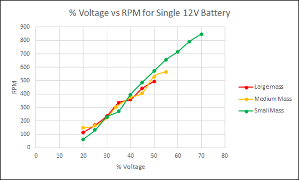
Figure 100 - % Voltage v. RPM (12V Battery)
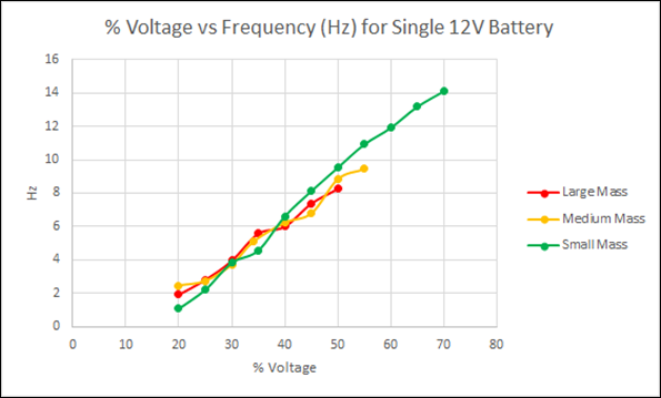
Figure 101 - % Voltage v. Hz (12V Battery)
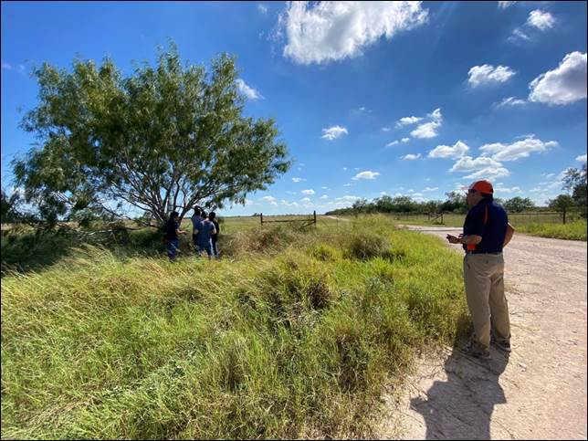
Figure 102 - Team at Work as Dr. Fuentes watches
from a Distance

Figure 103 - Miguel (Left), Joshua (Center), &
Paul (Right) Attaching Hook to Branch
NOTE: Natural Frequency (8
Hz) Equivalent Voltage %: ![]() = 44.6%,
= 44.6%, ![]() = 47.9%,
= 47.9%, ![]() = 48.6%
= 48.6%
NOTE: Bean Color (G-Green, Y-Yellow,
B-Brown)
NOTE: Hook placement is
measured in inches from beans to the hook. Hook placement is constant for tests
2, 3, & 5. Hook is placed close to the midpoint between trunk and beans.
NOTE: Time elapsed for tests 2,
3, & 4 is 30 seconds.
TEST
2 - Harvesting Efficiency @ Natural Frequency (8 Hz)
10/9/2021, Miguel
Martinez, Paul Silva, Benjamin Huerta, Joshua Sanchez
Purpose: This experiment serves to
determine the effectiveness of operating the device at the determined natural
frequency (8 Hz) of mesquite beans. This natural frequency was determined by
using FEA on mesquite bean models. Because of random differences between mesquite
beans, this model may not be entirely accurate. This experiment serves to test
the validity of this determined value of natural frequency.
Tools Required
o Adjustable
wrench
o Allen
wrench
o Assembled
device
o Small,
Medium, and Large offset masses
o Tape
measure
Procedure
1. Using the small offset mass,
approach a mesquite tree and find a representative branch with several mesquite
beans.
2. Measure and record the length from
the beans to the trunk, the circumference (or diameter) of the branch at the
midpoint between the beans and the trunk, the number of beans on the branch,
and color of the beans.
3. Hook the device at the midpoint
between the beans and the trunk and operate the device at the expected natural
frequency of the beans (8 Hz) for 30 seconds.
4. After the time has passed, count the
number of beans that were harvested from the branch.
5. Repeat this procedure for a total of
5 branches. After testing 5 branches, repeat the entire procedure again for the
medium and large offset masses.
6. Using the gathered data, determine
the harvesting efficiency in each branch by the following formula.
Harvesting Efficiency = # beans
harvested / # beans on branch initially
Table 9 - Harvesting Efficiency (@
Natural Frequency) for Small Offset Mass
|
|
Branch 1 |
Branch 2 |
Branch 3 |
Branch 4 |
Branch 5 |
|
Circumference |
5.5 |
- |
- |
4.7 |
- |
|
Branch Length |
108 |
- |
- |
39 |
101 |
|
# Beans on branch |
9 |
10 |
12 |
8 |
7 |
|
# Beans harvested |
0 |
0 |
0 |
1 |
1 |
|
Bean Color (G/Y/B) |
G |
G |
G |
B |
G |
Table 10 - Harvesting Efficiency (@
Natural Frequency) for Medium Offset Mass
|
|
Branch 1 |
Branch 2 |
Branch 3 |
Branch 4 |
Branch 5 |
|
Circumference |
- |
- |
- |
- |
- |
|
Branch Length |
- |
- |
- |
- |
99 |
|
# Beans on branch |
8 |
- |
- |
- |
7 |
|
# Beans harvested |
2 |
- |
- |
- |
0 |
|
Bean Color (G/Y/B) |
B |
- |
- |
- |
G |
Table 11 - Harvesting Efficiency (@
Natural Frequency) for Large Offset Mass
|
|
Branch 1 |
Branch 2 |
Branch 3 |
Branch 4 |
Branch 5 |
|
Circumference |
|
|
|
|
|
|
Branch Length |
|
|
|
|
|
|
# Beans on branch |
|
|
|
|
|
|
# Beans harvested |
|
|
|
|
|
|
Bean Color (G/Y/B) |
|
|
|
|
|
Results/Discussion: Though our experiments were cut
short due to the pole breaking off from the hook frame, there were several
observations we took note of. First, many of the vibrations were transmitted
onto the pole which made the pole hard to handle. In addition, these heavy
vibrations transmitted through the pole caused the speed controller to come
loose from the clamp mount multiple times. This made it very difficult to
control the frequency of the offset mass. Also, the wires connecting the speed
controller to the batteries and motor disconnected twice during experiments. Finally,
the connection between the pole and the hook frame broke off during one of the
experiments. Several factors led to this failure including having a relatively
small cross-section (1 inch long, 3/4" diameter end-piece) at this interface,
adding additional stress when pulling down pole during operation, as well as
having roll pins holding the two pieces (hook frame, pole) together. The
rotating unbalance mechanism did function as intended. The rotating offset mass
was able to generate vibrations, transmit them through the branch, and onto the
mesquite beans. Although a couple of mesquite beans fell due to the transmitted
vibrations, most stayed on the branch. This could be due to a variety of
factors including the beans not being ripe enough (ready to fall), not exciting
the mesquite beans at their natural frequency, and/or not having a strong
enough force inducing vibration. Some mesquite beans did seem to be
experiencing resonance but did not fall as a result. Another thing we noticed
is that the pole isn't needed once the device is hooked onto a branch. The only
purpose of the pole is to reach branches that are up high and hard to reach. Once
the hook is latched onto a branch, the pole is of no use. The
team is currently thinking of ways to implement a removable pole (that can
attach and detach from hook) or removing the pole from the design. Also, if the
hook is to be left on the branch on its own, we want to make sure it doesn't
fall off (secured tightly). Our next configuration/design will have the speed controller
separate from the hook/pole. This way, the device can be controlled from a
distance.
|
|
|
|
Figure 104 - Team Operating Device |
Figure 105 - Aftermath of Pole
Breaking Off |
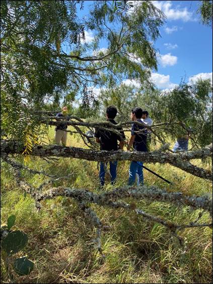
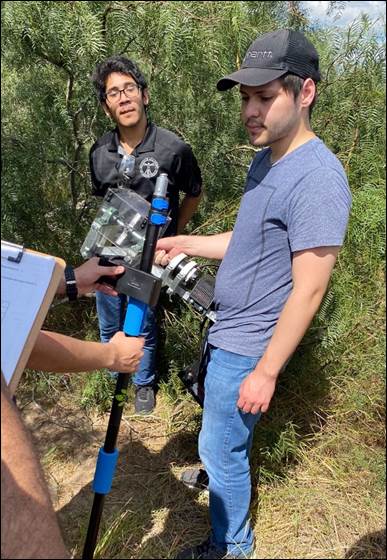
Change
in Approach
In addition to modifying the device,
the team intends on trying a different approach to harvesting mesquite beans. Our
initial approach was to continue the previous team's attempt to harvest
mesquite beans by exciting them (the beans) at their natural frequency. Due to
limited success thus far, the team wants to instead excite the mesquite
branches at their natural frequency and see if the mesquite beans fall as a
result. This will require some calculations to estimate the natural frequency
of different mesquite branches.
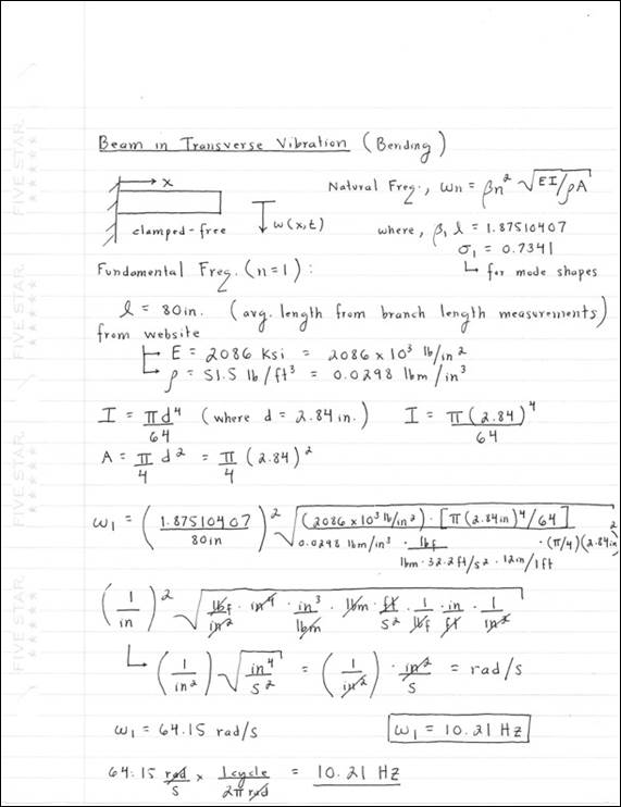
Figure
106 - Beam In Transverse Vibration Calculations
Click HERE to View Natural Frequency (Beam In
Transverse Vibration) Calculations.
The natural frequency calculations for
a cantilever beam (fixed-free) in transverse vibration (bending) are shown
above. The equation for the natural frequency (![]() ) was taken from a Vibrations
Textbook (Engineering Vibrations 4th Ed., Inman, D.J.). Note,
) was taken from a Vibrations
Textbook (Engineering Vibrations 4th Ed., Inman, D.J.). Note, ![]() is a constant given in the textbook. In
this case, we are assuming a mesquite tree branch to be a cantilever beam of
uniform circular cross-section, with constant density & elastic modulus. For
the calculations, a length of 80 inches was assigned as the length of the
branch. This length is the average length of mesquite tree branches (measured
from branch end to placement of hook) recorded during our visit to Zinnia Park.
The values for Elastic Modulus and Density were taken from a Scientific Website. In addition, a diameter of 2.84 inches
was considered for these calculations. Again, this is the average branch
diameter measured during our trip to Zinnia Park. Once all the parameters have
been assigned values, the fundamental frequency,
is a constant given in the textbook. In
this case, we are assuming a mesquite tree branch to be a cantilever beam of
uniform circular cross-section, with constant density & elastic modulus. For
the calculations, a length of 80 inches was assigned as the length of the
branch. This length is the average length of mesquite tree branches (measured
from branch end to placement of hook) recorded during our visit to Zinnia Park.
The values for Elastic Modulus and Density were taken from a Scientific Website. In addition, a diameter of 2.84 inches
was considered for these calculations. Again, this is the average branch
diameter measured during our trip to Zinnia Park. Once all the parameters have
been assigned values, the fundamental frequency, ![]() ,
yields a value of 64.15 rad/s or 10.21 Hz. This natural frequency is slightly
higher than that of mesquite beans.
,
yields a value of 64.15 rad/s or 10.21 Hz. This natural frequency is slightly
higher than that of mesquite beans.
To
investigate the relationship between branch length/diameter on the natural
frequency, a MATLAB code was developed.
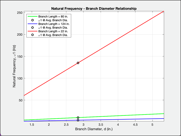
Figure 107 - Natural Frequency-Branch Diameter
Relationship
The
figure above depicts the relationship between the branch diameter and the fundamental
natural frequency of the mesquite branch at different branch lengths (Max.,
Avg., and Min. Branch Lengths Measured). The black circles show the corresponding
fundamental natural frequencies at a branch diameter of 2.84 inches (Avg.
Branch Diameter). From this graph, we can determine that the natural frequency
increases as the branch diameter increases (directly proportional). In
addition, the natural frequency increases as the branch length decreases.
However, we are not yet able to determine the type of relationship between the
branch length and natural frequency from this figure. Still, these are two very
important findings to take note of.
Natural
Frequencies of Mesquite Branch (@ Avg. Branch Diameter = 2.84 in.)
![]() (
(![]() = 80 in.) = 10.21 Hz (Avg. Length)
= 80 in.) = 10.21 Hz (Avg. Length)
![]() (
(![]() = 124 in.) = 4.25 Hz (Max. Length)
= 124 in.) = 4.25 Hz (Max. Length)
![]() (
(![]() = 22 in.) = 135.00 Hz (Min. Length)
= 22 in.) = 135.00 Hz (Min. Length)
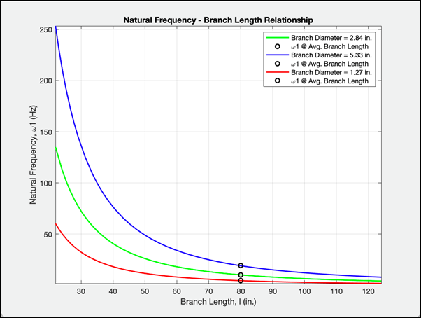
Figure 108 - Natural Frequency-Branch Length
Relationship
Figure
108 shows the relationship between the branch length and the fundamental
natural frequency of the mesquite branch at different branch diameters (Max.,
Avg., and Min. Branch Diameters Measured). The black circles show the
corresponding fundamental natural frequencies at a branch length of 80 inches
(Avg. Branch Length). In this case, the natural frequency seems to decrease
exponentially as the branch length increases. Furthermore, the natural
frequency increases as the branch diameter increases (directly proportional).
From this graph we can conclude that the relationship between the branch length
and the natural frequency is not linear, but exponential. From these figures,
the team has a better understanding of how the length and diameter of the
branches affects the natural frequency.
Natural
Frequencies of Mesquite Branch (@ Avg. Branch Length = 80 in.)
![]() (
(![]() = 2.84 in.) = 10.21 Hz (Avg. Diameter)
= 2.84 in.) = 10.21 Hz (Avg. Diameter)
![]() (
(![]() = 5.33 in.) = 19.16 Hz (Max. Diameter)
= 5.33 in.) = 19.16 Hz (Max. Diameter)
![]() (
(![]() = 1.27 in.) = 4.57 Hz (Min. Diameter)
= 1.27 in.) = 4.57 Hz (Min. Diameter)
Click
HERE To
View MATLAB Codes.
Harvester
Repair
The team began the repair phase by
using SolidWorks to perform a Finite Element Analysis on a stainless steel
flagpole which is adjustable in length (5 separate pole sections). This was
done not only to see whether the pole can sustain the 18-pound load (hook
assembly), but also how increasing/decreasing the length of the pole changes
the natural frequency of the system (pole). We don't want the pole to reach its
natural frequency during operation. The team believes the previous
configuration failed due to a combination of fatigue and the pole reaching its
natural frequency. In addition, the team redesigned the junction between the
hook assembly and the pole.
|
|
|
Figure 109 - Broken Hook-Pole
Connection |
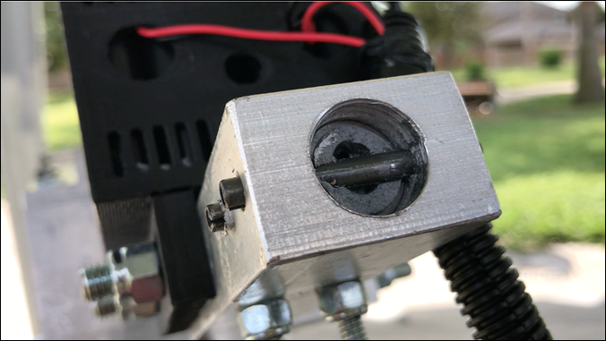
Hook Assembly - Pole Connection
Considering the stainless steel
flagpole is hollow and has different cross-section dimensions than the previous
pole, a new connector piece had to be designed to connect the pole to the hook
assembly. This new connector piece will have a larger cross-section at the base
to account for the flagpole's diameter (1 in.). Previously, roll pins were used
to fix the pole to the connector. In this case, two 1/4" bolts will be
used to secure the top end of the pole in place. Since the flagpole is hollow
(thin walled), we designed a filler piece (cylinder) to be inserted at the top
end of the flagpole. This will provide extra support for the bolts & pole.
This way, the bolts aren't just hanging on to the outer walls of the pole (pole
can shear easily). The pole will be bolted onto the connector, then the
connector will be inserted into the bottom end of the hook frame & bolted
in place. Below are the two new components designed on SolidWorks. Both
components will be made from 6061-T6 Aluminum.
|
|
|
|
Figure 110 - Connector Model |
Figure 111 - Filling Model |
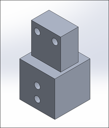
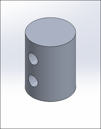
NOTE:
To View SolidWorks Part Drawing (Connector), Click HERE
NOTE:
To View SolidWorks Part Drawing (Filling), Click HERE
Static Analysis
Below are the results of the Static
Analysis conducted on the proposed design change. In this case, we are
considering a cast stainless steel flagpole made up of five 14.4" long
pole sections that piece together (6 feet in total length). The flagpole has an
outer diameter of 1 inch and a wall thickness of 0.030 inches (0.94" inner
diameter). An 18-pound load was applied on the top end of the pole (in
compression). This load represents the weight of the hook assembly. For this
simulation, the bottom end of the pole was fixed. Figure 113 shows the maximum
normal stress experienced by the pole (axial compression). The pole experiences
a compression stress close to 235 psi at the bottom end. The location of this
MAX stress is to be expected since the bottom end of the pole is supporting
everything above it (entire load). A stress of 235 psi is not concerning
considering cast stainless steel (AISI 316) has a yield strength of 29000 psi.
Mesh Parameters
|
Element Size |
Element Tolerance |
Total # of Elements |
|
0.2 in. |
0.01 in. |
52087 |
|
|
|
|
Figure 112 - Force Value Applied
(18 lbf) |
Figure 113 - Fixed Geometry
Applied |
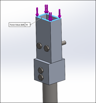
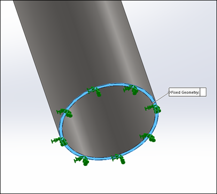
|
|
|
|
Figure 114 - Maximum Normal Stress
(Y-Direction) |
Figure 115 - Maximum von Mises
Stress |
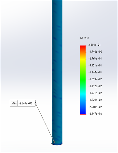
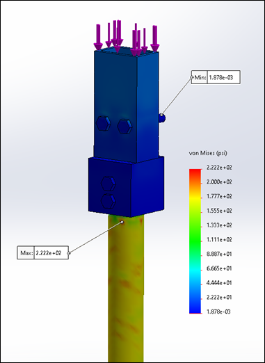
Figure 114 shows the maximum von
Mises Stress experienced by the pole. Von Mises stress is a value used to
determine if a given material will yield or fracture under load. The von Mises
criterion states that if the von Mises stress of a material under load is equal
or greater than the yield limit of the same material under simple tension then
the material will yield. In this case, the maximum von Mises stress for the
assembly (222 psi) is way below the yield limit of cast stainless steel (29000
psi). Therefore, there is no cause for concern. The maximum von Mises stress is
located near the top end of the pole. It should be noted that the connection
between the pole and the connector piece is where the previous assembly failed.
The team believes this design change will prevent this connection from failing
again.
|
|
|
Figure 116 - Maximum Axial Displacement
(Y-Direction) |
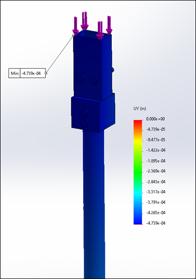
The figure above shows the maximum
axial displacement of the assembly (y-direction) as a result of the 18-pound
load applied from the top. Since the bottom end of the pole is fixed, the
maximum axial occurs at the very top of the assembly. The pole assembly
displaces approximately 0.000474 inches downward due to the applied load. This
value is considered negligible (less than one thousandth of an inch). These
results show that this design assembly will not fail due to excessive stresses
experienced from the weight of the hook assembly. Although these are just
simulations, the results shown give the team a better understanding of how the
pole will hold up due to the heavy load mounted on top (hook assembly).
Table 12 - Static Study Results
(Pole Assembly)
|
Max Normal Stress (psi) |
Max Von Mises Stress (psi) |
Max Axial Displacement (in.) |
|
234.7 (Compression) |
222.2 |
-0.4739 x 10⁻³ |
Frequency Analysis
Next, the team wanted to investigate
how changing the pole's length affects its natural frequency. Since the
flagpole is made up of 5 pole sections, we conducted a frequency analysis on
SolidWorks to determine the natural frequency of the pole at different lengths.
The purpose of the pole is to reach branches that are up high on a tree. Once
the hook is latched on to a branch, the pole is no longer needed. Having the
full length of the pole always attached to the hook assembly was a problem
during our first field test as the pole began shaking uncontrollably (reached
resonance) at certain frequencies. Therefore, we plan on shortening the length
of the flagpole (by removing sections) to change the natural frequency of the
system (pole).
In these simulations, each possible
length is considered (72 in., 57.6 in., 43.2 in., 28.8 in., & 14.4 in.).
The flagpole cross-section has an outer diameter of 1 inch and an inner
diameter of 0.96 inches. The flagpole is made of cast stainless steel (Young's
Modulus, E = 27.56 x 10⁶ psi). In each case, the pole sections have
an applied load of 18 pounds in compression at the top (weight of hook
assembly). The top of the pole is also fixed, considering this part will be
connected to the hook assembly which will be attached to a branch. We first
conducted the frequency analysis on the 6-foot pole (5 sections). The
fundamental natural frequency of the 6-foot pole was computed to be 7.2 Hz
which converts to 45.2 rad/s (Figure 118). This is concerning since this is the
frequency range we often operate the harvester at. This explains why the
previous pole was shaking a lot during the operation of the device. The pole
was at resonance and continued to absorb energy, which ultimately led it to
break off from the hook assembly. Now, the team will see how the natural
frequency of the pole changes as the pole length decreases.
|
|
|
|
Figure 117 - Force Value Applied
(18 lbf) |
Figure 118 - Fixed Geometry
Applied |
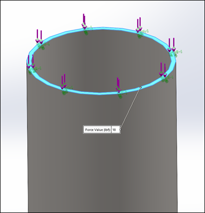
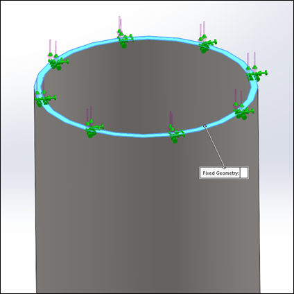
|
|
|
Figure 119 - Five Section Pole
Frequency Study (72 in.) |
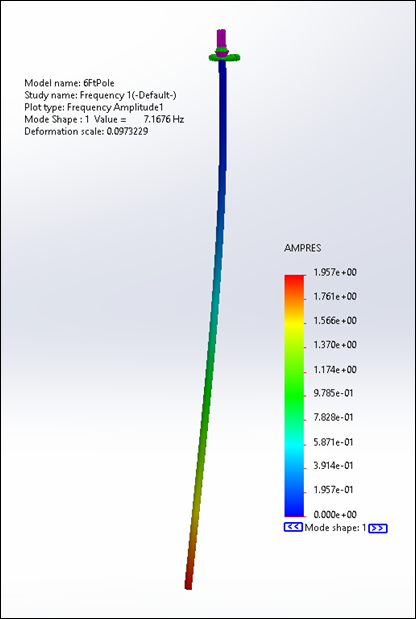
Mesh Parameters
|
Element Size |
Element Tolerance |
Total # of Elements |
|
0.25 in. |
0.0125 in. |
21030 |
|
|
|
Figure 120 - Four Section Pole
Frequency Study (57.6 in.) |
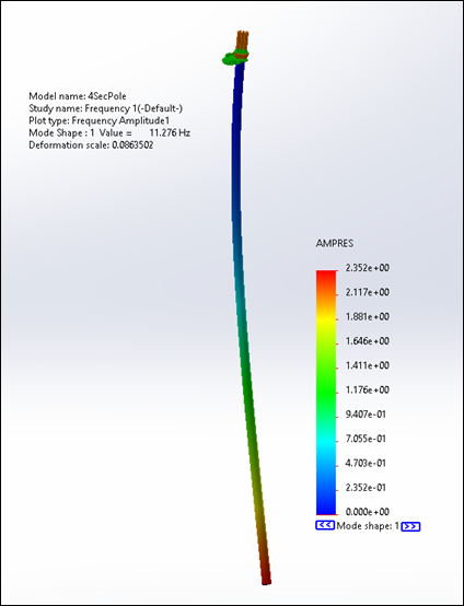
Mesh Parameters
|
Element Size |
Element Tolerance |
Total # of Elements |
|
0.2 in. |
0.01 in. |
26382 |
|
|
|
Figure 121 - Three Section Pole
Frequency Study (43.2 in.) |
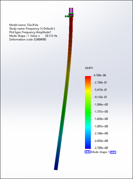
Mesh Parameters
|
Element Size |
Element Tolerance |
Total # of Elements |
|
0.15 in. |
0.075 in. |
36968 |
|
|
|
Figure 122 - Two Section Pole
Frequency Study (28.8 in.) |
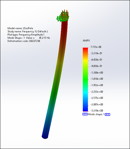
Mesh Parameters
|
Element Size |
Element Tolerance |
Total # of Elements |
|
0.15 in. |
0.075 in. |
24818 |
|
|
|
Figure 123 - One Section Pole
Frequency Study (14.4 in.) |
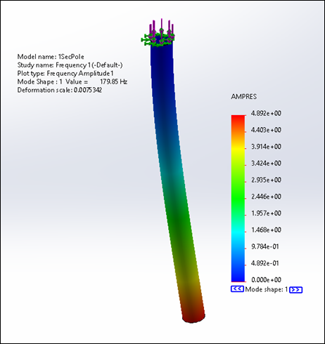
Mesh Parameters
|
Element Size |
Element Tolerance |
Total # of Elements |
|
0.1 in. |
0.005 in. |
26462 |
Table 13 - Frequency Study Results
(Natural Frequencies)
|
Pole Sections/Length (in.) |
Natural Frequency (Hz) |
|
5/72 |
7.2 |
|
4/57.6 |
11.3 |
|
3/43.2 |
20.1 |
|
2/28.8 |
45.2 |
|
1/14.4 |
179.9 |
The results above show the natural
frequency of the pole increasing as the length of the pole is decreased
(inverse relationship). This was expected since the stiffness of a structure increases
as its length is shortened. Since the natural frequency of a system is a
function of the stiffness and the mass (![]() ), the natural frequency of the pole
is directly affected by its length. In this case, the shortest pole length
(14.4 in. long) is the stiffest, and thus has the highest natural frequency. These
results are very important since it allows us to determine what pole lengths to
avoid while using the device. Since the device usually operates between 2 and 12
Hz, it is not recommended that we leave 5 or 4 pole sections attached to the
hook during operation. This can result in the pole reaching its resonant
frequency and shake uncontrollably. The pole will continue to absorb more and
more energy, causing unnecessary fatigue and stress to the connection between
the pole and the hook assembly, and eventually break. Therefore, it is best to
leave at most 3 pole sections attached during operation. Since the natural
frequency of 3 pole sections is approximately 20 Hz, we can ensure that the
driving frequency of the device does not match the natural frequency of the
pole. Of course, one can always attach additional pole sections when trying to
reach branches that are up high, as long as these additional sections are
removed prior to turning on the device. In addition, the device can be used
with less than 3 sections attached (two or one). This will further ensure that
the pole does not reach its natural frequency (considering the natural
frequency of one pole section is 180 Hz). Altogether, these simulation results
are critical in making sure the pole does not fail again.
), the natural frequency of the pole
is directly affected by its length. In this case, the shortest pole length
(14.4 in. long) is the stiffest, and thus has the highest natural frequency. These
results are very important since it allows us to determine what pole lengths to
avoid while using the device. Since the device usually operates between 2 and 12
Hz, it is not recommended that we leave 5 or 4 pole sections attached to the
hook during operation. This can result in the pole reaching its resonant
frequency and shake uncontrollably. The pole will continue to absorb more and
more energy, causing unnecessary fatigue and stress to the connection between
the pole and the hook assembly, and eventually break. Therefore, it is best to
leave at most 3 pole sections attached during operation. Since the natural
frequency of 3 pole sections is approximately 20 Hz, we can ensure that the
driving frequency of the device does not match the natural frequency of the
pole. Of course, one can always attach additional pole sections when trying to
reach branches that are up high, as long as these additional sections are
removed prior to turning on the device. In addition, the device can be used
with less than 3 sections attached (two or one). This will further ensure that
the pole does not reach its natural frequency (considering the natural
frequency of one pole section is 180 Hz). Altogether, these simulation results
are critical in making sure the pole does not fail again.
Machine Shop
Having conducted the appropriate
analysis on the proposed design changes, the team began machining the necessary
components. We first machined the connector piece on the mil. The original
aluminum piece had dimensions of 1.5" x 1.5" x 3". We had to trim down the top portion of
the piece for it to fit inside the bottom end of the hook frame. This was a
relatively simple process, considering the team had machined similar components
before. Once the top end was trimmed to specifications, we fit the piece inside
the hook and drilled the two 1/4" holes (where bolts will attach connector
to hook). We then drilled a 1" hole on the bottom end of the connector
(1.25 in. deep). This is where the first pole section will be inserted and
bolted on.
|
|
|
|
Figure 124 - Facing Connector |
Figure 125 - Trimming Connector |
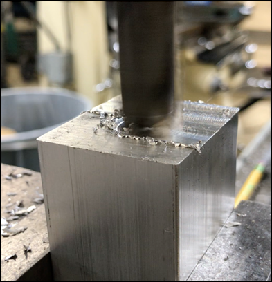
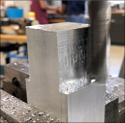
|
|
|
|
Figure 126 - Trimming Connector |
Figure 127 - Drilling 1/4"
(Through All) Holes into Connector |
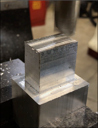

|
|
|
Figure 128 - Drilling 1" Hole |
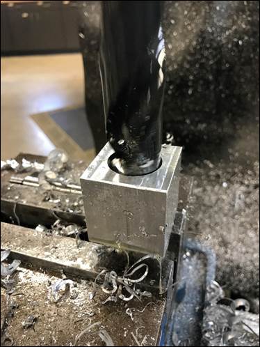
Next, we used the horizontal bandsaw
to cut the cylindrical piece length we need to create the filler (1.25 in.
length). The team then used the lathe to face the cylindrical piece down to
specification (0.94 in. diameter). Once the filler was finished, we pressed it
inside the top end of the first pole section. This is where the pole will be
bolted onto the connector. We then connected the pole with the filler inside to
the connector piece and drilled two 1/4" holes through the connector,
pole, and filler. These holes are for the bolts that will fix the connector,
pole, and filler together.
|
|
|
Figure 129 - Cutting Filler Piece
Length with Horizontal Bandsaw |
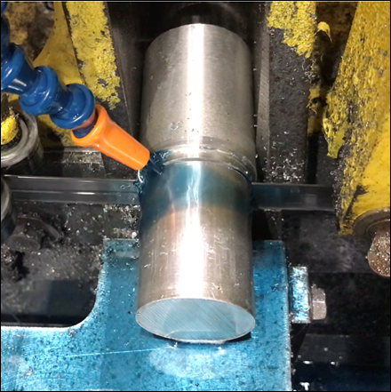
|
|
|
|
Figure 130 - Facing Filler with
Lathe |
Figure 131 - Trimming Filler
Diameter to Size |
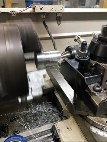
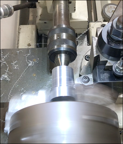
|
|
|
|
Figure 132 - Filler Piece |
Figure 133 - Filler inside Pole |
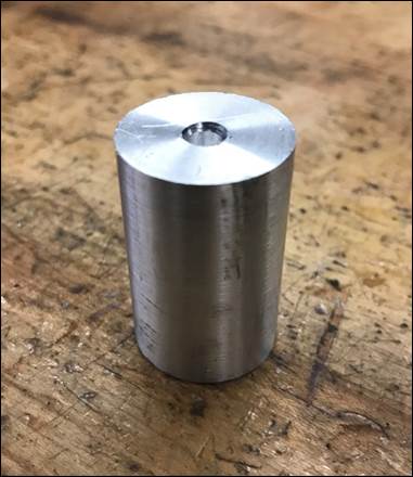
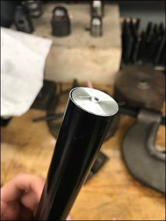
|
|
|
|
Figure 134 - Pole with Filler
inside Connector |
Figure 135 - Drilling 1/4"
Through All Holes |
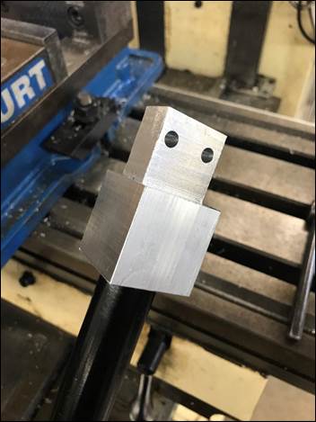
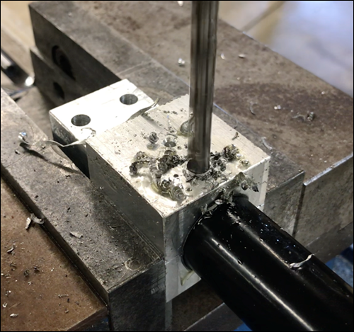
Finally, we secured the connector to
the hook frame as well as the pole to the connector with two 1/4" bolts
for each junction (1 5/8" long bolts for connector to hook frame and 2"
long bolts for pole to connector). Nylon insert lock nuts were used to tighten
the bolt in place. The team believes this connection between the hook frame and
the pole will be much stronger than the previous design. Now that the device is
fully repaired, we plan to go out to Zinnia park and begin testing on mesquite
trees again.
|
|
|
|
Figure 136 - Repaired Hook-Pole
Connection |
Figure 137 - Connector Close-Up |
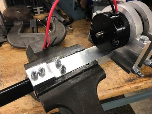
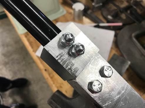
|
|
|
Figure 138 - Completed Repair |
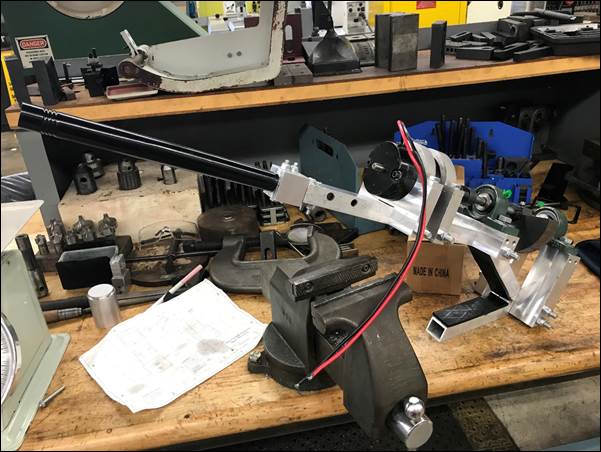
Field Testing
Prior to testing, the team made a
long "umbilical" cord to attach the motor and batteries to the speed
controller. This way, the speed controller can be detached from its pole mount
and be used from a distance (eliminates difficulty to control speed of device
due to heavy vibrations). At the park, the team latched the hook assembly onto
a mesquite tree branch, after which additional pole sections were removed (only
fixed pole section remained). Again, this is done to avoid reaching the natural
frequency of the pole and thus cause it to shake uncontrollably (causing
additional stress on the connector & pole). The speed controller was then
removed from its pole mount and used from a distance. This made it a lot easier
to control the speed of the device. The large offset mass was installed
throughout the experiments conducted at the park. Although there were few
mesquite beans still left on the trees, the team targeted branches that had
some. The team gradually swept through a variety of frequencies to examine the
effect on the mesquite beans. The circumference of the branch and the distance
between the hook and the beans was recorded. After sweeping through
frequencies, we took note of the range of frequencies that excited the mesquite
beans the most. Although this set of data is observational, it gives the team
an idea of what frequencies excite mesquite beans. We determined that lower
frequencies (25-35% Power) worked better than higher frequencies (40-55%
Power). Below are the results from our second field test. Still, the team plans
on conducting more experiments to gather & analyze more data.
Table 14 - Optimal Frequencies for
Branch Displacement by Observation
|
Branch |
Circumference (in.) |
Diameter (in.) |
Length (in.) |
Voltage Range (% Power) |
Frequency (Hz) |
|
1 |
8 |
2.546 |
110 |
50-55 |
8.253 |
|
2 |
9.25 |
2.944 |
150 |
45-55 |
7.37 |
|
3 |
7.875 |
2.507 |
107 |
30-40 |
3.95-5.576 |
|
4 |
6.25 |
1.989 |
75 |
30-40 |
3.95-5.576 |
|
5 |
10.75 |
3.422 |
90 |
32-35 |
4.6-5.576 |
|
|
|
Figure 139 - Hook Assembly Latched
on Branch |
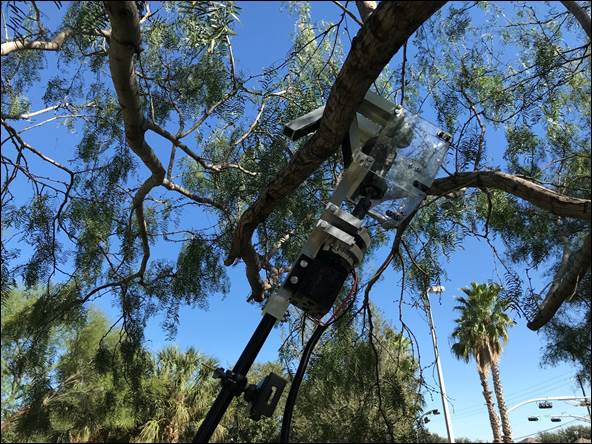
|
|
|
|
Figure 140 - Using Speed
Controller from a Distance |
Figure 141 - Harvester Shaking
Branch |
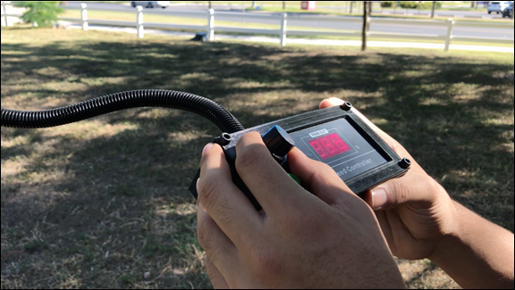
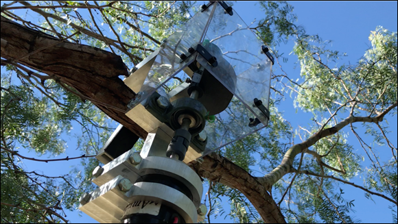
|
|
|
|
Figure 142 - Harvester Resting on
Branch |
Figure 143 - Harvester Hanging on
Branch |
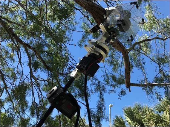
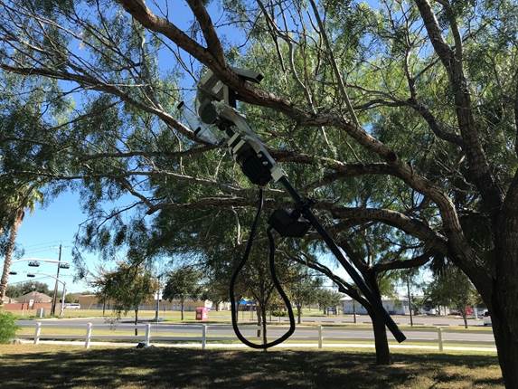
CHECK OUT our
Repair Process and Field Testing. See Video Below!
TEST
3 - Branch Acceleration
11/12/2021, Miguel
Martinez, Paul Silva, Benjamin Huerta, Joshua Sanchez
Purpose: This set of experiments
involves determining the acceleration experienced by a mesquite branch. In this
case, an accelerometer phone app (iOS) was used. The acceleration data obtained
can be used to estimate the forces experienced by the branch during operation.
Tools Required
o Accelerometer
Phone App
o Velcro
or Tape
o Phone
o Step
Stool
o Tape
measure
Procedure
1.
Mount
the accelerometer device (phone) onto a mesquite branch using Velcro or tape.
Measure the distance from the hook to the accelerometer and from the
accelerometer to where mesquite beans are hanging (or would be hanging). Also
measure the circumference of the branch (near hook).
2.
Note,
the phone is placed in such a way that the screen is facing the ground. This
will assign the acceleration in the x-direction as the acceleration of interest
(considering the harvester exerts the force transversely).
3.
Leave
hook hanging on branch (at angle).
4.
Start
measuring the acceleration and begin operating the harvester at 30% voltage for
15 seconds.
5.
Stop
measuring and export the data file once the 15 seconds are up.
6.
Repeat
steps 4-5 for varying voltages from 30% to 55%. Record all results.
7.
Next,
reposition the hook in such a way that the hook is hanging vertically
(perpendicular to the ground). Repeat steps 4-6 for this hook position.
8.
Finally,
leave hook hanging vertically and adjust the phone to be closer to beans.
Repeat steps 4-6.
9.
Plot
the results (acceleration v. time and force v. time) and determine the
steady-state force amplitude (in Newtons) for each test (18 in total). To
determine the force experienced by the branch, estimate mass of branch. Plot
the steady-state force amplitudes for each hook placement for varying voltage
percentages.
|
|
|
|
Figure
144 - Experimental Set Up 1 (Hook at Angle) |
Figure
145 - Experimental Set Up 3 (Phone Closer to Beans) |
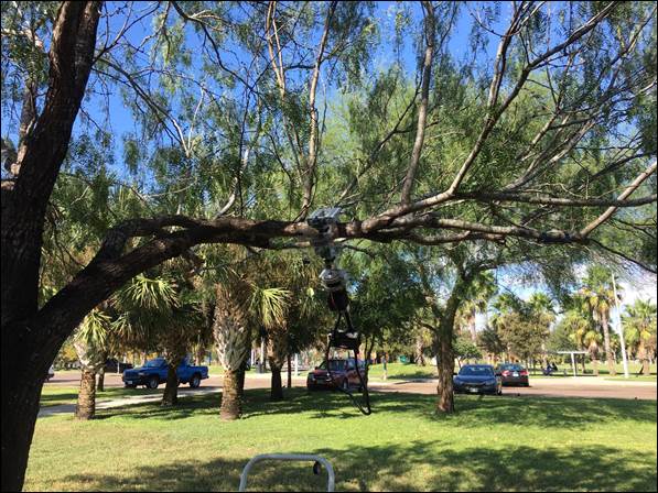
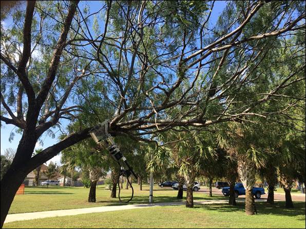
We ran 18 experiments; the results
are summarized in the table below.
Table 15 - Steady-State Force
Amplitudes
|
|
Test # |
SS Amp. (N) |
Voltage % |
|
Hook
at Angle (Left Alone) |
1 |
12.5 |
30 |
|
Hook to Phone: 43 in. |
2 |
18.5 |
35 |
|
Phone to Beans: 36 in. |
3 |
23.5 |
40 |
|
Hook to Beans: 79 in. |
4 |
27.5 |
45 |
|
|
5 |
28.5 |
50 |
|
|
6 |
27.5 |
55 |
|
Hook
Upright |
7 |
8.5 |
30 |
|
Hook to Phone: 43 in. |
8 |
15 |
35 |
|
Phone to Beans: 36 in. |
9 |
22.5 |
40 |
|
Hook to Beans: 79 in. |
10 |
34 |
45 |
|
|
11 |
N/A |
50 |
|
|
12 |
68 |
55 |
|
Hook
Upright (Phone Closer to Beans) |
13 |
11 |
30 |
|
Hook to Phone: 43 in. |
14 |
18.5 |
35 |
|
Phone to Beans: 36 in. |
15 |
12 |
40 |
|
Hook to Beans: 79 in. |
16 |
21.5 |
45 |
|
|
17 |
49 |
50 |
|
|
18 |
40 |
55 |
|
NOTE: Branch Circumference (at Hook): 3.26 in. Branch Circumference (at Phone):
1.75 in. |
|||
The first 6 experiments measured
acceleration of the branch with the hook at an angle. The following graphs were
obtained from Test 6.
|
|
|
|
Figure 146 - Accel. V. Time Graph
(Test 6) |
Figure 147 - Force V. Time Graph
(Test 6) |
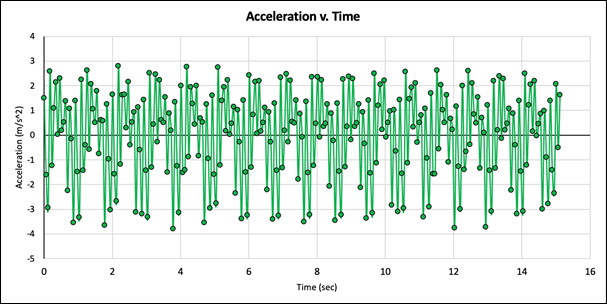
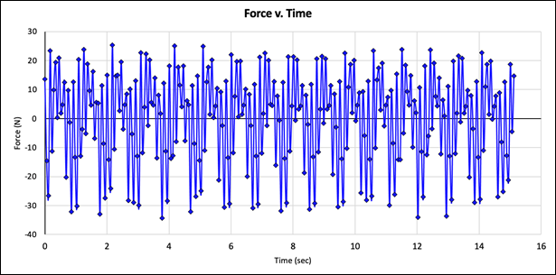
Experiments 7-12 tested the
acceleration with the hook held upright. The following graphs were obtained from
Test 12.
|
|
|
|
Figure 148 - Accel. V. Time Graph
(Test 12) |
Figure 149 - Force V. Time Graph
(Test 12) |
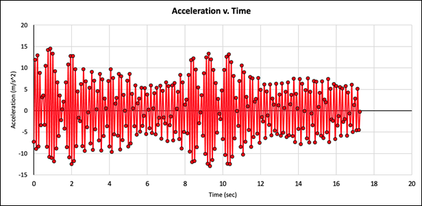
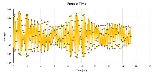
Experiments 13-18 tested the acceleration
with the accelerometer moved closer towards the beans. The following graphs
were obtained from Test 18.
|
|
|
|
Figure 150 - Accel. V. Time Graph
(Test 18) |
Figure 151 - Force V. Time Graph
(Test 18) |
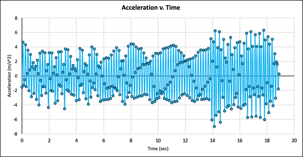
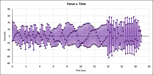
|
|
|
Figure 152 - Steady-State Force Amplitude
v. Voltage % Plot |
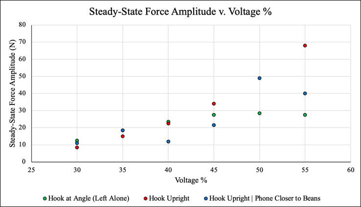
The plot above shows the
steady-state force amplitudes for each hook position at different voltage
percentages. This gives the team better insight as to what forces mesquite
branches are experiencing and what hook position can transmit the most force.
For the first set of experiments (Tests 1-6) the hook was mounted onto a
3.26-inch diameter branch, while the phone (accelerometer) was taped 43 inches
away, on a 1.75-inch diameter branch. The hook was then left alone, at an angle.
In this case, the force-amplitude increased initially with the voltage
percentage, then gradually plateaued at a force amplitude just below 30 N (6.74
lb). With the hook held vertically (upright), the force amplitude increased
linearly with the voltage percentage, reaching a maximum force of 68 N (15.29
lb) at 55% voltage. Finally, the hook was left upright while the phone was
moved closer to the beans. This resulted in an inconsistent trend of
force-amplitude values. The force-amplitude increased, decreased, then
increased again with voltage %. In this case, the largest steady-state
force-amplitude value (49N or 11.02 lb) is reached at a voltage percentage of
50. Overall, this graph shows the largest force is transmitted to the branch
when the hook is held in a vertical position, perpendicular to the ground.
Although this set of data does not
directly give us any information regarding the displacement or movement of the
mesquite beans or branch, we believe some of this information can be related to
the displacement of mesquite beans. The value of the acceleration of the branch
itself may provide useful information for harvesting mesquite beans. While we
do not have a method of determining whether a relationship exists between the
acceleration and the displacement of the branch, it is reasonable to assume
that there is a correlation. Based on this assumption, the values picked up by
the accelerometer can potentially be very useful in determining the
effectiveness of the device and likelihood that mesquite beans will
successfully be harvested at a particular frequency.
NOTE: Based on the calculations below,
there is some losses between the exerted force of the offset mass and the force
experienced by the branch. This is to be expected considering the mesquite
branch absorbs some of the force due to its stiffness.
Theoretical
Mass: m
= 2.86 lb = 1.297 kg
Eccentricity: e
= 1.03 in. = 0.026162 m
At 55% V, f
= 10.925 Hz = 68.643799 rad/s
Force: F
= (1.297 kg) x (0.026162 m) x (68.643799 rad/s)2 = 158.887 N = 35.9 lb force
Experimental
Mass of Branch (Estimated): m
= 20 lb = 9.07 kg
At 55% V, Steady-State
Acceleration, a = 7.5 m/s2
Force experienced by Branch: F
= (9.07 kg) x (7.5 m/s2) = 68 N = 15.29 lb force
Final
SolidWorks Model & Assembly Manual
|
|
|
Figure 153 - Hook Assembly Model
(Version 3) |
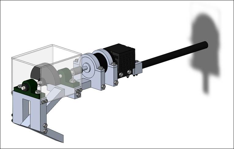
The figure above shows our final SolidWorks
Model of the Hook Assembly. This model includes our latest design changes
(connector, filler, steel flagpole) as well as additional components not
previously included (battery case, shaft collars, bolts, nuts). This SolidWorks
model provides an accurate representation of our final prototype and shows the
different components of the device. Having a detailed model of the device also
gives the team an opportunity to perform further analysis and put together a
step-by-step assembly manual.
Attached below is a Step-by-Step
Assembly Manual that shows how to put together the device. This will help guide
the user through the assembly process without encountering any problems. This
will also significantly reduce the assembly time of the device. Each Step has a
drawing included as well as the components involved in that step. In addition,
a written instruction manual has also been provided for the user. The team
believes these two assembly manuals are critical for the user to assemble the
device correctly. We also put together an assembly guide video that walks the
user through the assembly steps.
Click HERE to view Assembly Manual.
|
|
|
Figure 154 - Hook Assembly Model
(Side View) |
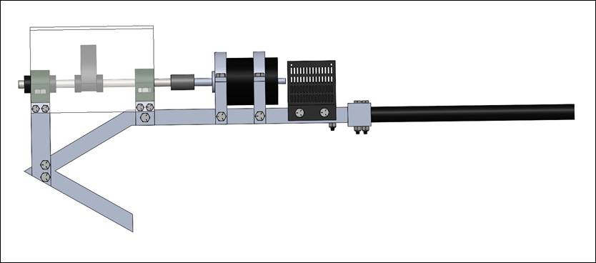
Click HERE to view Written Instruction Manual.
CHECK OUT our Assembly Guide Video Below!
CHECK OUT our Mechanical Mesquite Bean
Harvester Animation Below!
Sustainability
The team used SolidWorks to perform
a Sustainability Analysis on the Mesquite Bean Harvester. The material for each
component was specified in the software along with several other parameters
involving the manufacturing and assembly process. Chosen parameters are
summarized in the tables below.
Table 16 - Assembly Process
Parameters
|
Region of Assembly |
North America |
|
Built to Last |
5 years |
|
Region of Use |
North America |
|
Electricity Needs over Lifespan |
2 kWh/year |
|
Transportation |
Truck (2575 mi) |
Table 17 - End of Lie Parameters
(Estimated by Software)
|
Recycled |
25% |
|
Incinerated |
24% |
|
Landfill |
51% |
The results of the analysis are
given below.
|
|
|
|
Figure 155 - Carbon Footprint Results |
Figure 156 - Energy Consumption
Results |
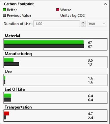
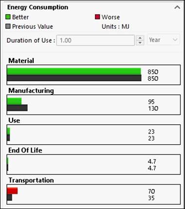
|
|
|
|
Figure 157 - Air Acidification
Results |
Figure 158 - Water Eutrophication
Results |
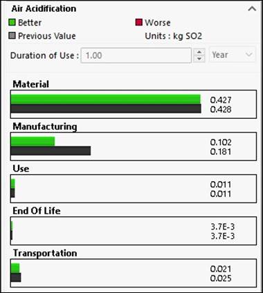
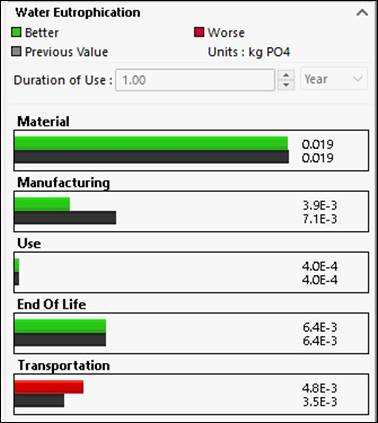
Click HERE to view Sustainability Report.
These results give us an idea of the
type of impact our device has on the environment. Sustainability improves the
quality of our lives, protects our ecosystem, and preserves natural resources
for future generations. We believe it's important have a working, yet
sustainable protype since it maximizes the benefits from an environmental focus
in the long-term.
Experiments
To Be Continued
NOTE: Below is a list of experiments we either did not get to
perform or believe should be performed during the peak of the Mesquite Bean
Harvest Season.
TEST
4 - Harvesting Efficiency @ Sweeping Frequencies
TBD, Miguel
Martinez, Paul Silva, Benjamin Huerta, Joshua Sanchez
Purpose: This test involves determining the
frequency (or range of frequencies) that excite mesquite beans the most. Since
all mesquite tree branches are different, the frequencies are not expected to
match up. The goal of this experiment is to determine a range of frequencies
which captures the natural frequency of most mesquite tree branches.
Tools Required
o Adjustable
wrench
o Allen
wrench
o Assembled
device
o Small,
Medium, and Large offset masses
o Tape
measure
Procedure
1. Using the small offset mass,
approach a mesquite tree and find a representative branch with several mesquite
beans.
2. Measure and record the length from
the beans to the trunk, the circumference (or diameter) of the branch at the
midpoint between the beans and the trunk, the number of beans on the branch,
and color of the beans.
3. Hook the device at the midpoint
between the beans and the trunk and operate the device at a 20% of the max
voltage for 30 seconds. The frequency in Hz can be determined by the collected
data in Test 1.
4. After the time has passed, count the
number of beans that were harvested from the branch.
5. Repeat this procedure on a total of
9 branches, each time with the % voltage increasing by 5% (from 20% up to 60%),
recording the results each time. Once completed, repeat the entire procedure
using the medium and large offset masses.
6. Using the gathered data, determine
the harvesting efficiency in each branch by the following formula.
Harvesting Efficiency = # beans
harvested / # beans on branch initially
Table 18 - Harvesting Efficiency (@
Sweeping Frequencies)
Offset
mass: S/M/L
|
Voltage
(%) |
Circumference
(in.) |
Branch
Length (in.) |
#
Beans on Branch |
#
Beans Harvested |
Bean
Color (G/Y/B) |
|
20 |
|
|
|
|
|
|
25 |
|
|
|
|
|
|
30 |
|
|
|
|
|
|
35 |
|
|
|
|
|
|
40 |
|
|
|
|
|
|
45 |
|
|
|
|
|
|
50 |
|
|
|
|
|
|
55 |
|
|
|
|
|
|
60 |
|
|
|
|
|
Results: TBD
TEST
5 - Effect of Hook Placement
TBD, Miguel
Martinez, Paul Silva, Benjamin Huerta, Joshua Sanchez
Purpose:
This experiment involves determining the optimum hook placement when operating
the device.
Tools Required
o Adjustable
wrench
o Allen
wrench
o Assembled
device
o Small,
Medium, and Large offset masses
o Tape
measure
Procedure
1. Using the small offset mass,
approach a mesquite tree and find a representative branch with several mesquite
beans.
2. Measure and record the length from
the beans to the trunk, the circumference (or diameter) of the branch at the
midpoint between the beans and the trunk, the number of beans on the branch,
and color of the beans.
3. Hook the device on a branch with
mesquite beans at 10 inches from the trunk and operate the device at the
determined natural frequency of the beans (8 Hz) for 30 seconds. Take note of
the displacement of the branch during operation.
4. After the time has passed, count the
number of beans that were harvested from the branch.
5. Repeat this procedure on a total of
8 branches, each time increasing the distance from the trunk by 10 inches
(testing distances from 10 inches to 80 inches). Once completed, repeat the
entire procedure for the medium and large offset masses.
6. Using the gathered data, determine
the harvesting efficiency in each branch by the following formula.
Harvesting Efficiency = # beans
harvested / # beans on branch initially
NOTE: Each Hook Placement is a different
branch.
Table 19 - Effect of Hook Placement
Offset
mass: S/M/L
|
Hook
Placement (in) |
Circumference
(in.) |
Branch
Length (in.) |
#
Beans on Branch |
#
Beans Harvested |
Bean
Color (G/Y/B) |
|
10 |
|
|
|
|
|
|
20 |
|
|
|
|
|
|
30 |
|
|
|
|
|
|
40 |
|
|
|
|
|
|
50 |
|
|
|
|
|
|
60 |
|
|
|
|
|
|
70 |
|
|
|
|
|
|
80 |
|
|
|
|
|
Results: TBD
TEST
6 - Time Elapsed for Beans to Stop Falling
TBD, Miguel
Martinez, Paul Silva, Benjamin Huerta, Joshua Sanchez
Purpose:
This experiment serves to determine the amount of time the device should be
hooked onto a branch during normal operation. The results will allow the
increase in efficiency when compared to hand-picking to be determined.
Tools
Required
o
Adjustable
wrench
o
Allen
wrench
o
Assembled
device
o
Small,
medium, and large offset masses
o
Tape
measure
Procedure
1. Using the small offset mass attached
to the assembly, approach the mesquite tree and hook the assembly interface
around the branch at approximately the middle of the branch length.
2. Measure the circumference of the branch
that's being tested on before activating the hook assembly.
3. Turn on the hook assembly and set up
the speed dial to 8 Hz for the small offset mass.
4. If practical, count the number of
beans initially on the affected branch before running the hook assembly.
5. Keep track of the number of beans
that fall in the first 30 seconds.
6. Keep track of the number of beans
that fall for the next few 30 second intervals until a total time of 2 minutes
has elapsed.
7. Stop
the run with the OFF/ON button.
8. Remove
the assembly from the branch and set it down to remove the polycarbonate casing
around the small offset mass with an adjustable wrench. Use the same tool to remove the screws
supporting the upper pillow block.
9. Remove
the clamps next to the offset mass with an Allen wrench and loosen the screw
that is attaching the mass to the shaft.
10. Slide
off the pillow block, clamps, and offset mass.
11. Insert
the medium offset mass and slide back the clamps then the pillow block.
12. Tighten
the clamps, screw in the medium offset mass, and screw the pillow block to its
mount.
13. Follow
the procedure by running the small offset mass and apply it to the medium offset
mass.
14. Once
done recording the data needed for the medium mass, apply the procedures
mentioned earlier to remove and replace the medium offset mass with the large
one, followed by conducting the test run with the large offset mass.
NOTE: For the entire 2
minutes elapsed, it will be dedicated to a single branch. Three separate branches will be tested
with the 3 different offset masses (one for each size).
NOTE: Test 5 is at the
natural frequency (8 Hz). Recall ![]() = 44.6%,
= 44.6%, ![]() = 47.9%,
= 47.9%, ![]() = 48.6%
= 48.6%
Table
20 - Time Elapsed for Bean Harvesting
Offset
mass: S/M/L
|
|
Circumference
(in.) |
Branch
Length (in.) |
|
Branch
1 |
|
|
|
Time
Elapsed |
# Beans on Branch |
Beans Harvested |
Bean Color (G/Y/B) |
|
30
seconds |
|
|
|
|
1
minute |
|
|
|
|
1
minute 30 seconds |
|
|
|
|
2
minutes |
|
|
|
Results: TBD
TEST
7 - Battery Life
TBD, Miguel
Martinez, Paul Silva, Benjamin Huerta, Joshua Sanchez
Purpose: This test involves determining the
battery life of the product. This will allow the user to have an estimate of
how long the device should last under normal operating conditions. The results
of this experiment will be compared to the theoretical battery life. The
batteries are listed by the vendor to be 2000 mAh. We will use this assumption
in the theoretical calculation and determine by testing if this is accurate.
Tools
Required
o
N/A
Procedure
Our protocol for this experiment is
to run the motor continuously (without the hook and mass attachment to prevent
damage to the hook and other components) at its expected operating voltage. The
motor will run continuously until either failure or a significant decrease in
speed. This time will be measured and used to determine the battery life of the
device.
Results: Based on our theoretical
calculations and the assumption that each battery is 2000 mAh, we expect that
the battery life will be ___ hours of continuous use. Assuming that the device
will be operated for ___ hours a day, the device is expected to last for ___
days without charging.
[1] Ramos, Mary.
"The Ubiquitous Mesquite, " Texas Almanac, Texas
State Historical Association (TSHA), 2007, https://texasalmanac.com/topics/environment/ubiquitous-mesquite
[2] "Plant Database -
Prosopis glandulosa, " Lady Bird Johnson Wildflower Center,
6 November 2015, https://www.wildflower.org/plants/result.php?id_plant=prgl2
[3] "The Amazing Mesquite
Tree, " Cappadona Ranch, 7 March 2017, https://cappadonaranch.com/blogs/blogs/the-amazing-mesquite-tree
[4] "Mesquite - The
Wonder Tree, " An Eye for Texas, 29 March 2011, https://aneyefortexas.wordpress.com/2011/03/29/mesquite-the-wonder-tree/
[5] DuHamel, J.
"Mesquite Trees provide Food, Fuel, Medicine, &
More, " Arizona Daily Independent News Network, 7 July
2013, https://arizonadailyindependent.com/2013/07/07/mesquite-trees-provide-food-fuel-medicine-and-more/
[6] "Rotating
Unbalance, " Virtual Labs - An MHRD Govt of India Initiative, http://mdmv-nitk.vlabs.ac.in/exp6/index.html
[7] Niklas, K.J., 1992, Plant
Biomechanics - An Engineering Approach to Plant Form and Function, The
University of Chicago Press.
[8] James, K.R., Dahle, G.A.,
Grabosky, J., Kane, B., Detter, A., 2014, Tree Biomechanics Literature Review:
Dynamics, Arboriculture & Urban Forestry 40(1), 1-15.
[9] Dargahi, M., Newson, T.,
Moore, J.R., 2020, A Numerical Approach to Estimate Natural Frequency of Trees
with Variable Properties, MDPI Forests 11, 1-21.
[10] 2010, Frequency Response
of Trees, Dept. of Civil and Environmental Engineering MIT, 1-31.
[11] Baker, C.J., 1997,
Measurements of the Natural Frequencies of Trees, Journal of Experimental
Botany 48(310), 1125-1132.
[12] Ganji, H.D., Ganji, S.S.,
Ganji, D.D., Vaseghi, F., 2011, Analysis of Nonlinear Structural Dynamics and
Resonance in Trees, Shock and Vibration 19, 609-617.
[13] Loghavi, M., Khorsandi,
F., Souri, S., 2011, The Effects of Shaking Frequency and Amplitude on
Vibratory Harvesting of Almond, ASABE.
[14] Ni, H., Zhang, J., Zhao,
N., Wang, C., Lv, S., Ren, F., Wang, X., 2019, Design on the Winter Jujubes
Harvesting and Sorting Device, MDPI Applied Sciences 9, 1-17.
[15] James, K.R., Haritos, N.,
Ades, P.K., 2006, Mechanical Stability of Trees under Dynamic Loads, American
Journal of Botany 93(10), 1522-1530.
[16] Polat, R., Gezer, I.,
Guner, M., Dursun, E., Erdogan, D., Bilim, H.C., 2006, Mechanical Harvesting of
Pistachio Nuts, Journal of Food Engineering 79, 1131-1135.
Here is a summary of important
Senior Design files. These files include our Project Websites, our Reviews
during Senior Design I & II, and other Project Videos.
SDI
REVIEWS
MIDTERM & FINAL
Index Page & Design
Process Page (Current Website)
SDII
REVIEWS
MIDTERM & FINAL
Index Page & Design
Process Page (Current Website)
OTHER
VIDEOS: Welcome
Video, Project
Overview, Prototype1
ACKNOWLEDGEMENTS
We would like to recognize and
thank several people whose help was critical to the team's success.
Dr. Noe Vargas (Senior Design
II Professor) - Guided team
throughout Senior Design, gave us advice on several different aspects of the
project, and provided us access to the Makerspace during the build stage.
Dr. Arturo Fuentes (Faculty
Advisor) - Regular feedback
and engineering advice regarding mesquite harvester. Constant support
throughout the project. Always gave us his thoughts on our proposed ideas and
suggested we try different methods to excite the mesquite beans.
Dr. Joanne Rampersad-Ammons
(Faculty Advisor) - Regular feedback
and information regarding mesquite harvester. Helped us understand the importance of
this project and the impact it can have.
Mr. Gregory Potter (Senior
Design II Assistant Professor) -
Advice for improving prototype.
Mr. Hector Arteaga (Machine
Shop Technician) - Machine shop
training and general help throughout
manufacturing process. Gave us his thoughts regarding different ways to
manufacture certain components. Helped the team a lot during build stage and
got the team involved with machining.
Mr. Jose Sanchez (Mechanical
Engineering Professor) - TIG
welded aluminum hook for the team.
Cappadona Family - Helped team by showing us the mesquite bean harvesting
process and how they process the beans to make different products. Showed us
around their ranch and allowed us to test our device there. We had lots of fun
and learned a lot from them.