UTRGV / COLLEGE
OF ENGINEERING AND COMPUTER SCIENCE / MECHANICAL ENGINEERING DEPARTMENT
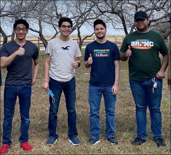
TEAM 9 - Design of a Mechanical Mesquite Bean Harvester

|
SDII Students (L-R) |
o
Paul Silva o
Miguel Martinez o
Benjamin Huerta o Joshua Sanchez |
|
Faculty Advisors |
o Dr. Arturo Fuentes o Dr. Joanne Rampersad-Ammons |
|
Course Instructors |
o
Dr. Noe
Vargas Hernandez o
Mr. Greg
Potter |
|
College of Business and Entrepreneurship Collaboration |
o Dr. Sylvia Robles (Instructor) o Daniel Castillo o Felipe Montemayor |
WHAT IS THE PROBLEM WE ARE TRYING TO SOLVE?
WHY IS THIS PROBLEM IMPORTANT?
LEARN MORE ABOUT OUR DESIGN PROCESS
Welcome!
We are Team 9, "Ripple Effect". Our project is titled, "Design
of a Mechanical Mesquite Bean Harvester". The mesquite bean harvester is a
mechanical device designed to provide an efficient harvesting technique that
will expedite the mesquite bean harvesting process. The mechanical harvester will
significantly reduce the time and manual labor necessary to harvest mesquite
bean pods every harvest season.
|
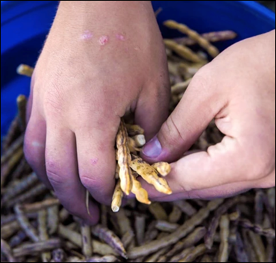
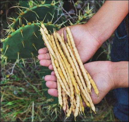
Figure
1 - Collected Mesquite Beans |
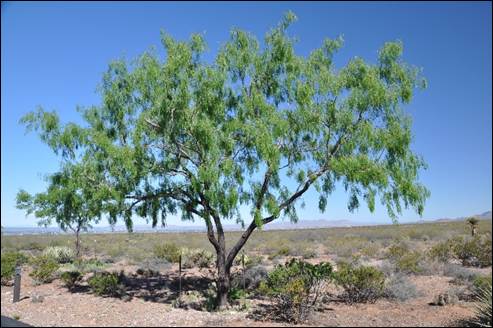
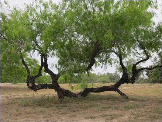
Mesquite
is one of the most widely distributed trees in the state of Texas. Of all the
Mesquite in the United States, 76 percent grows in Texas. The most prevalent of
this subset is the honey mesquite (Prosopis glandulosa).
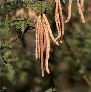
The mesquite tree produces beans which mature in late summer and develop in a
long, yellowish-brown pod between four and ten inches long. They are harvested
and turned into a variety of delicious and highly nutritious mesquite bean
products such as jellies, flour, tea, and coffee.
|
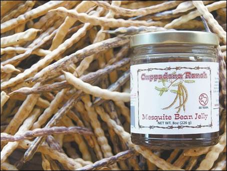
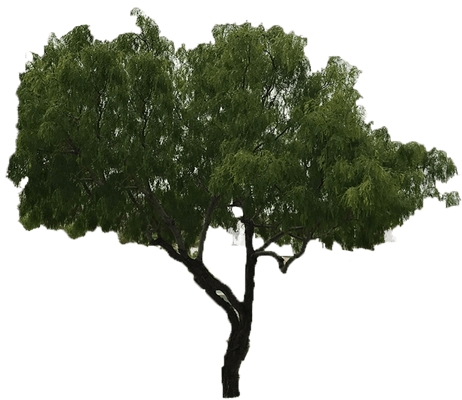
Figure
2 - Honey Mesquite Tree on Texas Field |
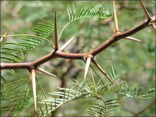
Figure
3 - Mesquite Seedpods Hanging from Branch |
|
Figure
4 - Cappadona Ranch Mesquite Bean Jelly |
|
Current mesquite bean harvesting
methods are performed primarily by hand. This technique is labor-intensive,
dangerous (large, sharp thorns on mesquite trees may cause injury), and inefficient.
Hand-picking mesquite beans requires a lot of effort and time from the part of
the farmers. Manually harvesting mesquite beans is not necessarily something
that can help a farmer increase its mesquite bean yield and thus their supply
of mesquite bean products.
|
Figure 5 - Cappadona
Family Hand-picking Mesquite Beans |
Therefore, our task is to develop a
device capable of harvesting mesquite beans in a much more efficient manner. This
will not only save time for mesquite farmers, but also provide a safer
alternative to hand-picking. The rest of this webpage contains more information
about our project and the approach we took. We hope that you will find this
project interesting and fun.
Watch our Welcome Video Below!
In collaboration with the Business
Team - Mesquite Bean Harvest.
CLICK HERE to View Business Model & Value
Proposition.
Farmers across the RGV who harvest
(or are looking to harvest) mesquite beans for mass production of a product
need an effective, mechanized solution for harvesting mesquite bean pods.
Traditional mesquite bean harvesting
methods are performed primarily by hand. This process is not ideal for mass
harvesting since it takes lots of time picking bean pods one-by-one. In
addition, mesquite trees have huge, vicious thorns which may cause injury
during manual harvesting. The amount of physical effort required to perform
this harvesting process is challenging and not very efficient. With a limited
mesquite bean harvesting process, a business is not able to grow and expand its
supply of mesquite bean products to others in a mass quantity.
|
Figure 6 - Farmers Hand-Picking
Beans |
Figure 7 - Harvested Mesquite Bean
Pods |
To better understand the problem, we
conducted background research on the following relevant topics.
From this we learned the following:
Mesquite Trees & Beans
o Mesquite
trees are a tough, resilient plant species that thrive across the American
Southwest. Of all the Mesquite in the United States, 76 percent grows in Texas.
The most prevalent species in Texas is the honey mesquite (Prosopis glandulosa).
o Honey
Mesquite trees vary considerably in size, depending on growing conditions &
their environment. In cases where water is plentiful, and the seedlings are not
damaged by weather or wild animals, trees can grow up to 50 feet tall, with a
branch spread of 40 feet or more.
|
Figure
8 - Mesquite Tree with Complex Geometry |
o Mesquite
trees tend to grow into very complex geometries. Usually, the trunk "forks"
a few feet above the ground, causing the tree to grow out in all directions. In
some cases, if a new shoot is disturbed, the tree develops into a sprawling
multi-trunked shrub.
o Mesquite
trees are armed with sharp, stout thorns up to two inches long that emerge from
the base of the leaf stems.
|
Figure
9 - Mesquite Tree Thorns |
o Mesquite
trees possess several characteristics that help it thrive in the toughest environments.
The arid conditions of the southwest have been ideal for the mesquite, since it
requires little water, and has developed several adaptations that help it
survive prolonged droughts.
o One
of these adaptations is the tree's root system. Mesquite maintains two set of
roots - extremely long taproots to reach deep water sources, and broad, shallow
roots to capture water from brief rain events. Their taproots will find
subsurface water at depths of 200 feet below the surface, while the surface
roots extend 50 feet or more past outer edge of the crown (branch width). The
reach of their roots has given mesquite trees a considerable advantage in
desert-like environments. Their wide-spreading, deep-rooted systems enable the
tree to improve its germination and growth in xeric conditions.
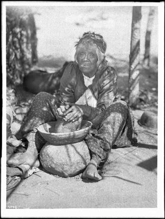
o Mesquite
trees have long been used by Native Americans across the Southwest for a bevy
of things including food, beverages, medicine, glue, firewood, construction
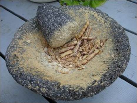
material, and more. The native people grounded mesquite beans and pods into
meal and high protein flour. In addition, Native Americans also collected and
boiled mesquite flowers to make tea. Mesquite gum, herbage, roots, and bark
were all used in medicinal applications. Mesquite wood serves as an excellent
fuel source and was sought after by many Native American groups. The Native
people were able to take full advantage of the many useful resources the
mesquite tree has to offer. It therefore earned the title, "Tree of Life".
|
Figure
10 - Native American Woman Grounding Mesquite Beans |
Figure
11 - Metate and Mano (Stone Bowl and Tool used to grind mesquite beans) |
Cappadona Ranch Visit
o
Problems with Current Technique (Hand-Picking)
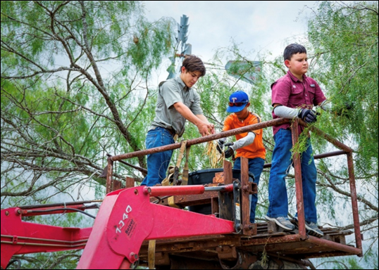
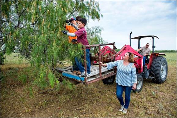
Very
tiring (especially due to the hot, humid weather). Must always watch out for
sharp thorns. Inefficient due to accessibility of mesquite beans. Mesquite
trees grow in a variety of shapes and forms. Some are somewhat straight and
grow upward, while others grow into a thicket of swirly branches which are
almost impenetrable. This causes some difficulty in trying to pick the mesquite
beans off the trees. Some are almost impossible to get to
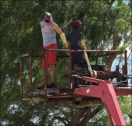
due to the way the tree is formed. Right now, a tractor with an elevation
platform is used to reach the beans that are way up high. Overall, very tedious
process that requires a lot of effort.
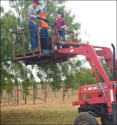
|
Figure
12 - Cappadona Family on Tractor Platform Picking
Beans by Hand |
To learn more about Cappadona Ranch, Click HERE.

Vibrating Mechanisms
(Rotating Unbalance)
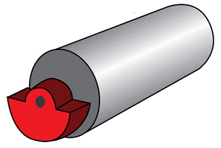
o There
are many different mechanisms that are used to induce vibration. One of the
most common methods involves a rotating unbalance. Rotating unbalance is
defined as the uneven distribution of mass around an axis of rotation.
o Unbalance
is caused when the center of mass (inertia axis) is out of alignment with the
center of rotation (geometric axis). When an object is forced to spin about a
fixed axis and the mass is not evenly distributed about that fixed axis, then a
centrifugal force develops and induces an excitation force that causes
vibration within a structure.
|
Figure
13 - Eccentric Rotating Mass |
Figure 14 - Rotating Unbalance (Motor) |
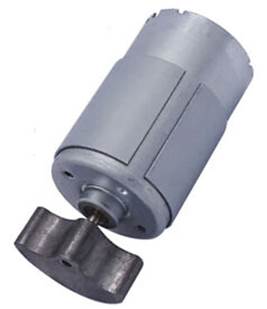
o Small
irregularities in the distribution of a mass in the rotating component of a
machine can produce substantial vibration. A rotating unbalance can be
represented as a mass, ![]() ,
rotating with an angular velocity,
,
rotating with an angular velocity, ![]() ,
at a distance,
,
at a distance, ![]() ,
from the center of rotation.
,
from the center of rotation.
Competitive
Products
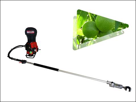
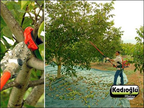
Currently, mechanical harvesters
exist for various types of fruits and nuts (apples, walnuts, pecans, olives,
etc.). Although there are no
devices specifically designed to harvest mesquite beans, there are devices
which are used to harvest other products (fruits/nuts) in a similar manner.
Within the current market, there are a couple of harvester devices that can
potentially be used to harvest mesquite beans in addition to their intended
use. Below is an image of a Kadioglu EMR400 Branch
Shaker Harvesting Machine, which is used to harvest walnuts from trees. Although
this device is not meant to harvest mesquite beans, it is something that can be
analyzed as such.
|
|
|
|
Figure 15 - Kadioglu
EMR400 Branch Shaker Harvesting Machine |
|
Click HERE to view product website.
Our main motivation to work on the
mesquite bean harvester is to expedite the mesquite bean harvesting process by
designing a device capable of harvesting mesquite beans at a more efficient clip.
This will lead to a significant increase in harvested mesquite beans and enable
farmers to mass produce their mesquite bean products. With farmers mass
producing their mesquite bean products to supermarkets (HEB, Walmart, Sprouts,
etc.) across the region, their local business can grow & expand its revenue
beyond what it currently is.
This device can also be found attractive to those who have several mesquite trees within their property and are looking to make some money. Mesquite farmers often receive many calls regarding people offering their mesquite trees with ready-to-harvest beans. The problem is, farmers aren't necessarily looking to go pick beans on other people's property, they want the person themselves to harvest the mesquite beans and sell the harvested beans to them (per pound). This device can help some of those people who want to harvest mesquite beans in an efficient manner and sell them to farmers within the region.
In addition, mesquite beans are
considered a superfood; meaning it provides excellent health benefits from an
exceptional nutrient density. Mesquite bean products contain lots of nutrients
and can help people eat a much healthier diet.
|
Figure 16 - Cappadona
Family Picking Mesquite Beans one-by-one. |
Figure 17 - Mesquite Bean Flour is
diabetic friendly (contains natural sugar with high fiber and protein
content) |

|
Figure 18 - Stakeholder Map |
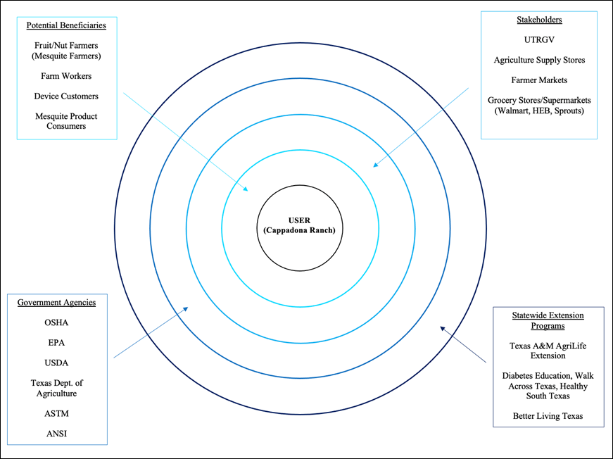
The figure above illustrates the
people, companies, and organizations that will be affected in one way or
another by the product we develop. During the development of this product, we
must consider all those who have some connection to this device.
"We
propose the design of a mechanical mesquite bean harvester to expedite the
labor-intensive, time-consuming process of hand-picking. "
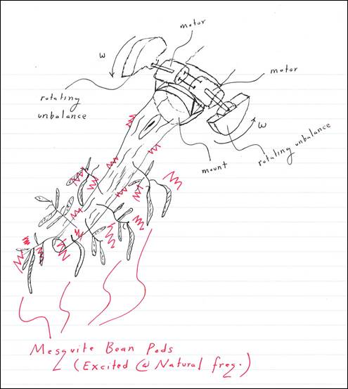
After understanding the problem in
depth, we explored various potential solutions. We utilized an evaluation
procedure to help us select the most effective concept. Our proposed solution
will utilize a rotating unbalance to generate vibrations, which will excite the
mesquite beans attached to a branch, causing them to fall. Furthermore, the
fallen mesquite beans will be collected by a catching mechanism located beneath
the branch. Together, these two mechanisms will enable farmers to efficiently
harvest mesquite beans.
|
Figure 19 - Rotating Unbalance
Sketch |
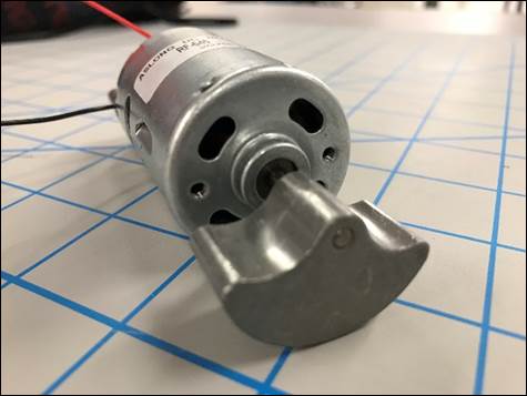
|
Figure 20 - Rotating Unbalance (DC
Motor) |
Once we defined a clear solution
idea (concept), the team applied its engineering knowledge to transform it into
a real product.
|
|
|
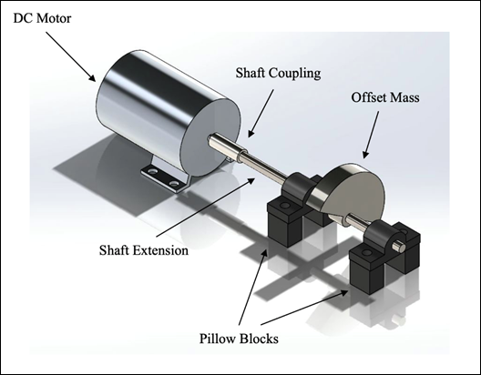
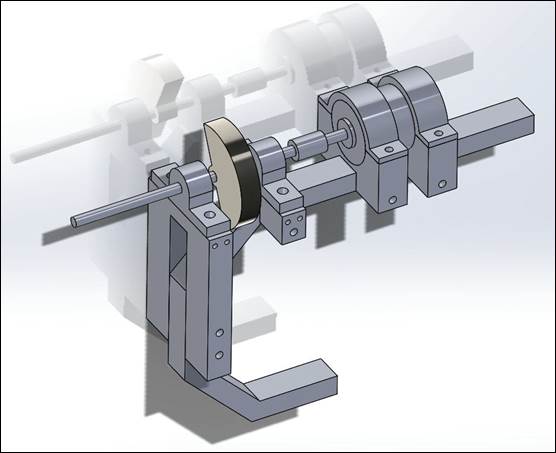
Figure 21 - Motor Assembly Model |
|
|
|
Figure 22 - Motor Assembly Model
(Side View) |
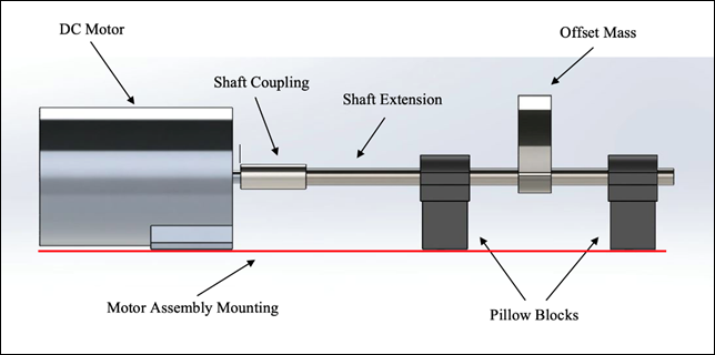
The two figures above depict the
motor assembly configuration developed on SolidWorks. This model gives the team
an idea of how the motor, offset mass, and pillow blocks will be positioned on
the device. In this case, two pillow blocks are mounted on each side of the
offset mass. This will provide additional support to the system as the offset
mass is rotating and generating a force.
The team designed several different
offset mass shapes on SolidWorks to evaluate how their shape affects the
generated force. Since the generated force depends on the mass of the object
and the distance between the axis of rotation (center of circle) and its center
of mass, we wanted to see which mass will generate the largest force (given
certain constraints). After conducting some calculations, we determined offset
mass 3 to be our best option. Although offset mass 3 didn't have the largest
eccentricity, its mass was large enough to generate the largest force of the
sample offset masses (given constant rotational speed).
|
|
|
|
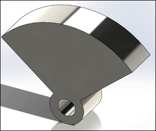
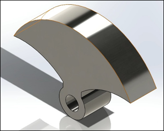
Figure 23 - Offset Mass 1 |
Figure 24 - Offset Mass 2 |
|
|
|
|
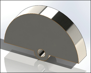
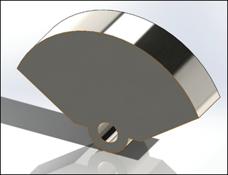
Figure 25 - Offset Mass 3 |
Figure 26 - Offset Mass 4 |
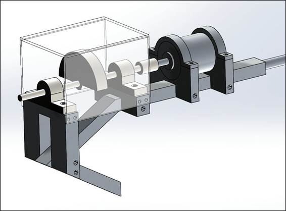
Figure
27 - Hook Assembly Model (Version 1)
Figure 27 shows our first SolidWorks
Hook Assembly model. This gave the team a better understanding of how each
component will be mounted to work as a system. The SolidWorks components
previously designed were modified to the dimensions of the materials purchased
(DC Motor, Pillow Blocks, Shaft, & Coupling). To attach the motor and
pillow blocks to the hook, different mounts were designed. These were
relatively simple mounts that can be bolted onto the hook (removable). The hook
shown above was designed by the previous team. Although this design looked
promising to us, discussions with our faculty adviser made us realize that the
hook had a fixed width and was not compatible with branches of various sizes.
This geometry is not ideal since the hook is only able to attach to branches of
one specific size. In addition, the hook was made of solid aluminum which meant
it would be heavy. The team decided it was best to redesign the hook based on
measurements (circumference/diameter) from actual mesquite tree branches as
well as perform the appropriate analysis to see if a hollow hook would be safe
to implement (can it handle the expected forces/vibration).
Figure
28 - Hook Assembly Model (Version 2)
After visiting Zinnia Park and
taking measurements of several mesquite tree branches, we came up with a range
of diameters for the hook to attach to. We also performed a finite element
analysis on SolidWorks and determined that a hollow aluminum hook frame should
be ale to withstand the generated forces. Therefore,
we decided to implement a hollow, tapered hook into our design. This new hook
will be significantly lighter and capable of latching onto branches of various
sizes. The figure above shows our updated our hook assembly model. Some changes
include implementing the newly designed tapered, hollow hook, reducing the
thickness of the motor mounts (top and bottom), modifying the upper pillow
block mount (to fit redesigned hook), and surrounding the offset mass with a
polycarbonate case (safety). Again, this SolidWorks model gives the team a
better understanding of how each component will be put together to function as
one. The team will now work to manufacture and assemble the harvester based on
this design.
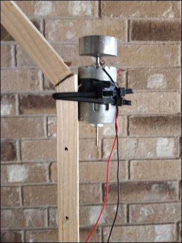
Early Experiments
Since this is a continued project,
the team found that it was best to perform experiments to gather appropriate
data for analysis. Using a motor with an offset mass (rotating unbalance used
in massaging chairs), a mesquite tree, harvested mesquite beans, and a power
supply, the team was able to put together a series of experiments that helped
us understand how the mesquite beans are excited as well as the different frequencies
of excitation. Ideally, we want to match the driving frequency with the natural
frequency of the mesquite beans. Below are some of the experimental setups we
were able to carry out.
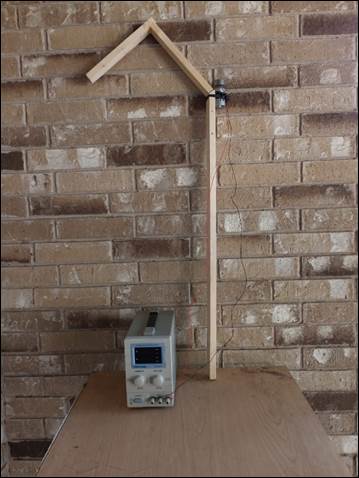
Experiment 1:
|
Figure 29 - Rotating Unbalance
attached to Branch |
Figure 30 - Mesquite Beans
attached to Subbranches (via rubber bands) |
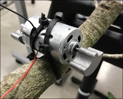
Due to not having possession of a
mesquite branch at the time, experiment was performed on oak tree branch. Motor
was zip-tied to branch end. Mesquite beans were attached to branch with rubber
bands. Beans were excited through a range of frequencies (via motor voltage
adjustment). Response of mesquite beans was observed.
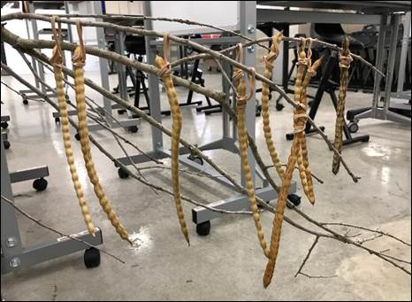
Experiment 2:
|
Figure 31 - Mesquite Beans
attached to Subbranches (via rubber bands). Rubber Bands fixed to subbranch
with tape. |
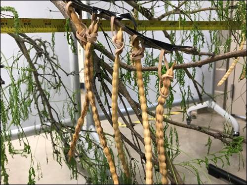
The second experiment was performed
on a mesquite tree branch. Because beans (with rubber band) tended to slide
down the subbranch during excitation, rubber bands were now fixed to subbranch
through tape. This way, the initial conditions of the beans remain constant.
Experiment was performed through same range of voltages (motor speeds).
Excitation of beans was recorded for close observation.
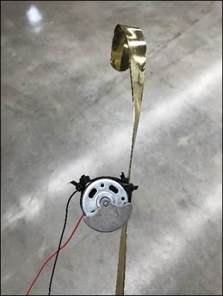
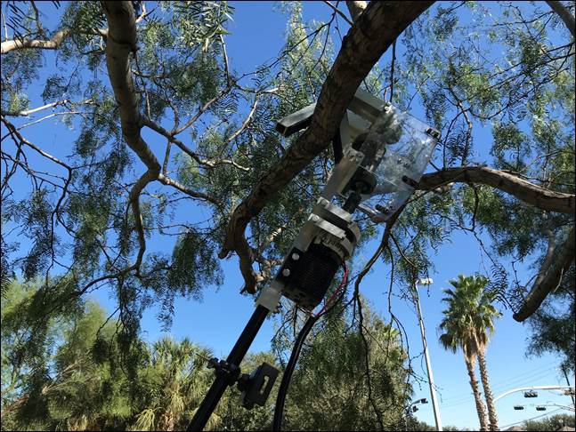
Experiment 3:
|
Figure 32 - Rotating Unbalance
attached to Hook |
Figure 33 - Mesquite Beans
attached to Subbranches (via hot glue) |
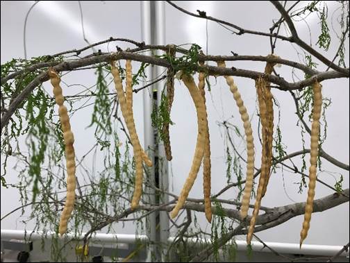
For our latest experiment, the
mesquite beans were now attached to the subbranch with hot glue. This was to
try to limit the influence of the rubber bands on the response of the mesquite
beans. In addition, the motor was attached to a hook to examine how the beans
will respond to more realistic conditions. With access to a tachometer, we
measured the rotational speed of the motor throughout the range of operating
voltages. The team also investigated how the position of the motor on the hook
changed the direction of vibration and thus how the mesquite beans are excited.
Prototype 1 - After testing, a prototype of the hook and motor
was built. This prototype serves to help the team in determining the proper
dimensions and orientation of each of the components that will be used in the
final design. The orientation of the offset mass is positioned so that the
vibration causes bending motion in the mesquite beans.
|
|
|
|
Figure 34 - Hook
Prototype |
Figure 35 - Hook
Prototype (Close Up) |
CHECK
OUT our Prototype 1
Video. See Video Below!
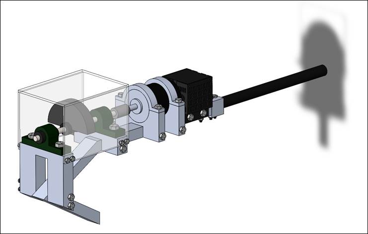
Motor
Assembly 1 & 2 (CAD):
Creating the following motor
assembly models on solid works gives the team a general idea of the configuration
that will be mounted on the side of the extender pole. The components involved
in this assembly include a DC Motor, a Shaft Coupling, a Shaft Extension, Two
Pillow Blocks, and an Offset Mass. The pillow blocks are implemented to bear the
forces generated by the rotating offset mass. The motor assembly will be
mounted in such a way that the offset mass is positioned alongside the tree
branch. This way, the force generated is transmitted directly towards the
branch the hook is attached to. The placement of the offset mass is subject to
change. Whether it stays on the outside of both pillow blocks or if it is repositioned between the two pillow blocks will
depend on the static analysis (solid mechanics) performed (see Design Process
Page).
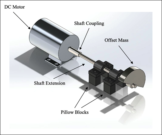
Figure
36 - Motor Assembly 1

Figure
37 - Motor Assembly 2
Rotating
Unbalance Summary:
Governing Equation: ![]()
Generated Force: ![]()
Parameters:
(![]() ) - mass of the system (kg)
) - mass of the system (kg)
(![]() ) - damping coefficient (kg/s)
) - damping coefficient (kg/s)
(![]() ) - stiffness of the system (kg/s2)
) - stiffness of the system (kg/s2)
(![]() ) - offset (unbalance) mass (kg)
) - offset (unbalance) mass (kg)
(![]() ) - eccentricity (m)
) - eccentricity (m)
(![]() ) - driving frequency (rad/s)
) - driving frequency (rad/s)
t - time (sec)
(![]() ) - translational acceleration (m/s2)
) - translational acceleration (m/s2)
(![]() ) - translational velocity (m/s)
) - translational velocity (m/s)
(![]() ) - translational displacement (m)
) - translational displacement (m)
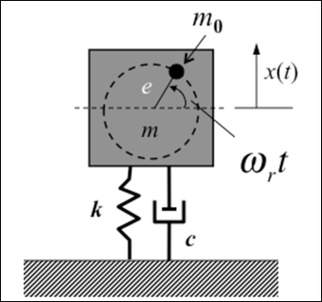
Figure
38 - Rotating Unbalance Diagram
On the left side of the governing
equation, we have the mass of the overall system (![]() ), the damping coefficient (
), the damping coefficient (![]() ), and the stiffness of the system (
), and the stiffness of the system (![]() . Here, it's important to mention
that the "system" that is represented in this project is the hook
that the motor assembly will be mounted on. Moreover, the (
. Here, it's important to mention
that the "system" that is represented in this project is the hook
that the motor assembly will be mounted on. Moreover, the (![]() ) represents the acceleration of the
system, (
) represents the acceleration of the
system, (![]() ) represents the velocity, and (
) represents the velocity, and (![]() ) represents the displacement of the
system.
) represents the displacement of the
system.
The right side of the governing
equation includes the mass of the rotating unbalance (![]() , the eccentricity (
, the eccentricity (![]() ) (distance from the axis of
rotation to the center of mass), and the driving frequency (
) (distance from the axis of
rotation to the center of mass), and the driving frequency (![]() ). Collectively, these parameters
make up the force magnitude, as shown above. The force magnitude is multiplied
by a sinusoidal function in which the period of oscillation is determined by
the driving frequency (time dependent function).
). Collectively, these parameters
make up the force magnitude, as shown above. The force magnitude is multiplied
by a sinusoidal function in which the period of oscillation is determined by
the driving frequency (time dependent function).
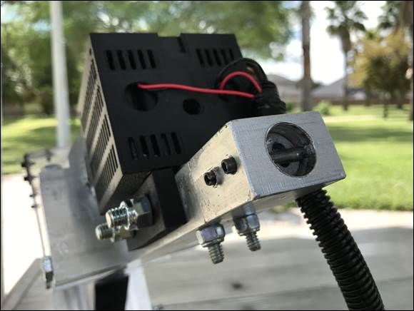
Prototype 2 - With new information and ideas, the team began working in
the machine shop to develop the second prototype. This version improves upon
the first one in several ways. The new prototype is mainly composed of aluminum
with the hook being composed of hollow aluminum tubing. The rotating unbalance
motor was replaced with a regular DC motor with a custom-made offset mass
attachment to induce vibrations. In addition to being more robust, it can
produce much stronger vibrations. It includes a speed controller which allows
the user to easily adjust the vibration frequency by using a dial.
Manufacturing
Procedure:
1.
Mill
all the metal blocks to its border size (rectangular prisms), then mill out all
the corners and right angles of the block pieces.
2.
Drill
all the holes of all the pieces with the smallest diameter specified in the
blueprints, then all the holes with the next biggest diameter, and so on (until
all holes of all sizes are drilled).
3.
Apply
the same practice with the holes that require threading (use tap drills and
taps).
4.
Finally,
angle the Milling machine to manufacture the slanted geometries of the
appropriate metal pieces.
5.
Other
pieces with curved geometries were first subject to the vertical bandsaw and
then the belt sander.
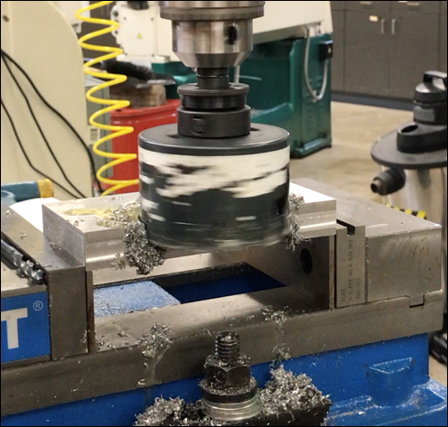
Figure 39 - Cutting 3" Hole
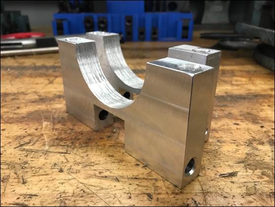
Figure 40 - Lower Motor Mounts
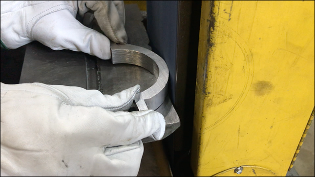
Figure 41 - Shaping Outer Curvature
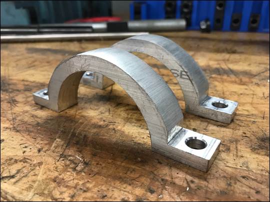
Figure 42 - Upper Motor Mounts
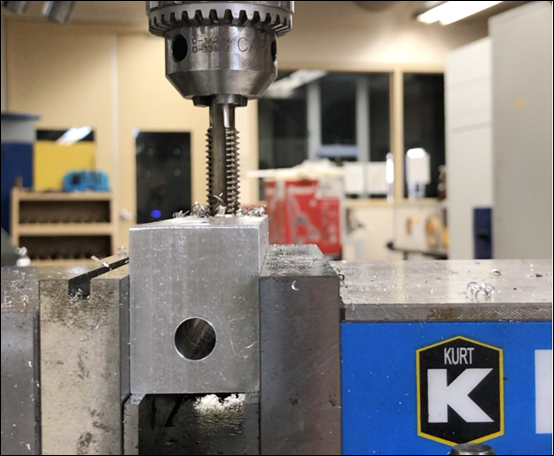
Figure 43 - Using Tap to Create Threads
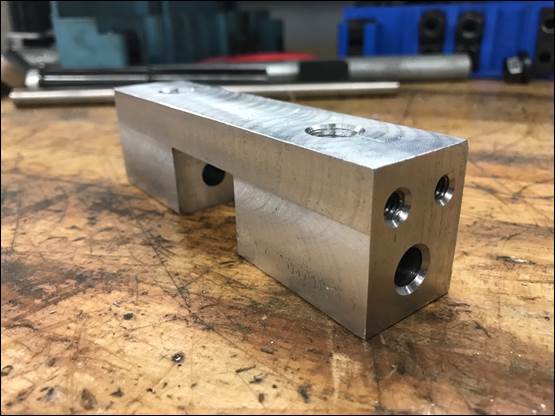
Figure 44 - Lower Pillow Block
Mount
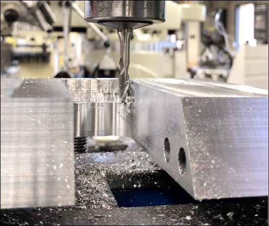
Figure 45 - Trimming Slot Edges on
Upper Pillow Block Mount
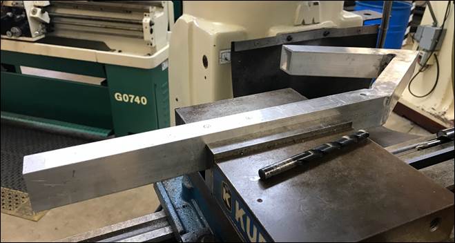
Figure 46 - Hook Frame
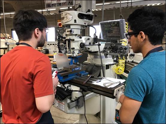
Figure 47 - Ben (Left) & Paul (Right)
Milling
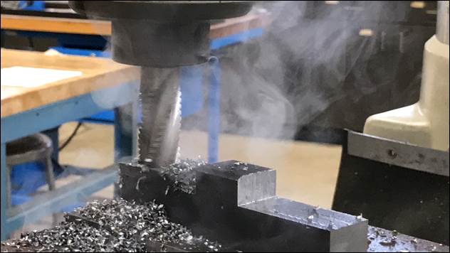
Figure 48 - Milling Offset Mass
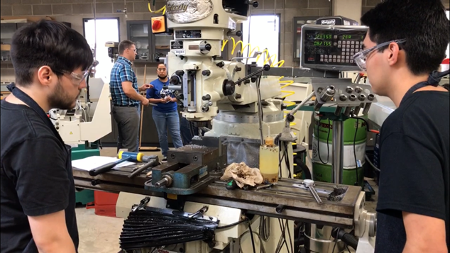
Figure 49 - Ben (Left) & Miguel (Right)
Milling
Assembly Procedure:
1.
Align
and screw the lower motor mounts to the main hook frame.
2.
Align
and screw the pillow block mounts to the main hook frame.
3.
Place
the motor securely on top of the lower motor mounts, making sure that the wires
from the motor don't get crushed/pressed against.
4.
Make
sure the coupler is locked; this will connect the two shafts securely from the
motor.
5.
Apply
the upper motor mounts and screw them to a tight fit on the lower motor mounts.
The motor should then be stable and not slide from its position.
6.
Slide
in the lower pillow block into the shaft and on top of its respective mount.
7.
Screw
it to keep it in place with the adjustable wrench.
8.
Insert
the first clamp that will be next to the mass, then the offset mass itself,
then the other clamp on the other side of the mass.
9.
Make
sure that the clamps are right next to the offset mass and use the Allen wrench
to lock them in place.
10.
Make
sure the hole of the offset mass is aligned with the hole in the shaft and use
a screw to tighten it in place. This allows the torque to be transmitted.
11.
Slide
in the upper pillow block through the shaft and on top of its respective mount.
12.
Screw
it securely using the adjustable wrench.
13.
Hover
the polycarbonate casing around the offset mass and screw it onto the assembly
with an adjustable wrench.
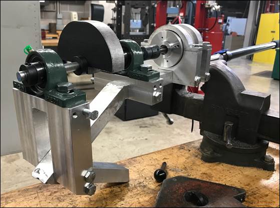
Figure 50 - Assembled Hook without Case
3D Printing
After assembling all the
mechanical components of the hook device, the team shifted its focus towards
the electronics. The team designed a battery case that will house both
batteries and be mounted directly behind the motor. In addition, to control the
speed of the motor, a speed controller will be used. The speed controller must
be easy to use and not have wires exposed. The team therefore decided to design
a case for the speed controller that will house the speed controller along with
the ON/OFF button and potentiometer. The speed controller will be mounted on
the pole to allow the user access to the controls.
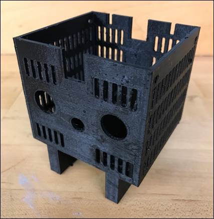
Figure 51 - Battery Case
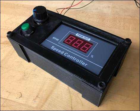
Figure 52 - Speed Controller inside Case
CHECK
OUT
the Manufacturing Process. See Video Below.
CHECK
OUT
the 3D Printing Process. See Video Below.
Field
Test at Cappadona Ranch
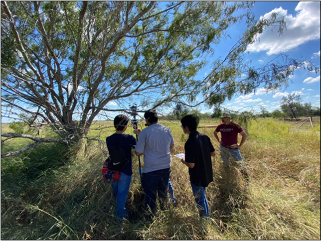
Figure
53 - Team Setting Up Device
After each individual component was
assembled onto the hook/pole, the team conducted a field-test. Our designed
experiments were cut short due to the pole breaking off from the hook.
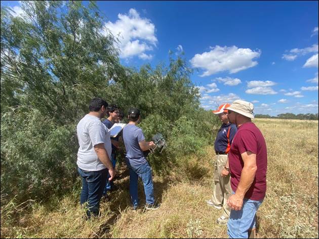
Figure 54 - Team Discussing Broken Device
Minimal data was collected. Team is
looking to modify design to make it more rugged. Wiring and controller came
loose multiple times during experiments. We noticed that the pole shook a lot
during experiments and was not needed once hook was attached to branch. Team is
therefore considering having a removable pole or removing the pole from the
design. In addition, we intend on trying a different approach to harvesting.
Instead of exciting the beans at their natural frequency, we will look to
excite the branch at its natural frequency and evaluate the results. We are
continuing to work on the device to make sure it is effective in harvesting mesquite
beans.
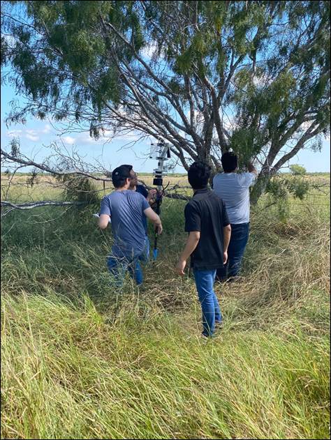
Figure 55 - Team Attaching Hook to Mesquite
Branch
Repair
|
|
|
Figure
56 - Pole-Hook Connection Failure |
Although the team was mildly upset by this setback, it
was a valuable moment for the team as we were able to identify a
weakness in the hook assembly design. Up until this point, most of our physical
simulation test runs from SolidWorks were used to find the stresses and
deflections that the hook frame experienced; such simulation runs were
not performed for the pole yet. After the hook-pole interface broke, the team
began discussion pertaining to the cause of failure. It was agreed
that the most probable cause of failure was a combination of fatigue and the
pole reaching its natural frequency. We followed up this discussion by
brainstorming different ways we could repair the harvester. Several ideas
were proposed to fix the hook-pole interface including a welded joint
and an aluminum hook insert fastened by bolts. The team decided to move forward
with a flagpole as the pole that will attach to the hook assembly. The flagpole
is made of stainless steel and is adjustable in length (5 separate pole
sections). The team believes adjusting the length of the flagpole will help us
avoid the natural frequency of the pole. In addition, shortening the length of
the pole will make the device much easier to handle. The team began redesigning
the hook-pole junction to work with the new pole.
Redesign of Hook-Pole
Connection
|
|
|
|
Figure 57 - Connector Model |
Figure 58 - Filling Model |
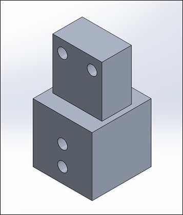
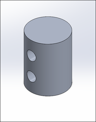
The connector is designed
to allow a hollow steel tube to be bolted on. A cylindrical filler will be
inserted inside the top end of the hollow flagpole. The aluminum filler is
used to provide extra support to the flagpole as it is bolted onto the
connector piece. This design improves upon the previous design by providing
a more rigid connection between the pole and the hook assembly. Previously,
roll pins were used to fix the pole in place. This time, two bolts will be used
to secure the pole to the bottom portion of the connector.
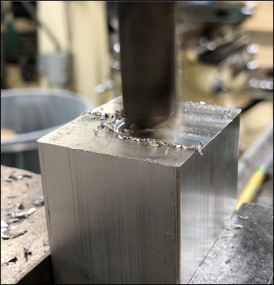
Return to the Machine Shop
After performing static
and frequency studies on the newly designed hook-pole interface, the team
returned to the machine shop to machine the necessary components. Considering
the team had machined similar components before, this repair process was
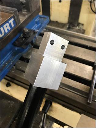
relatively straightforward. We used the mill to face and trim the connector piece
to spec. The connector piece will be inserted into the bottom end of the hook and
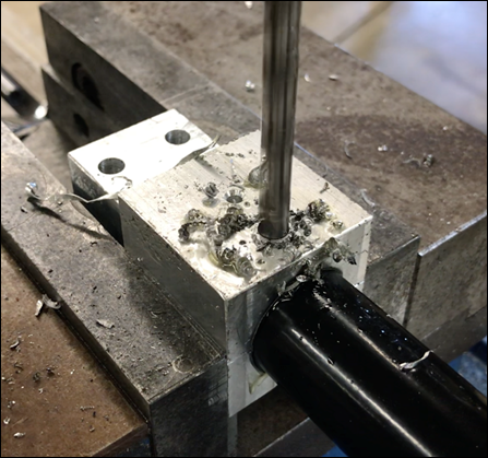
fixed in place using two bolts. A 1 inch hole was
drilled into the bottom side of the connector piece to allow the flagpole to be
inserted.
|
|
|
|
Figure
59 - Facing Connector |
Figure
60 - Trimming Connector |
|
|
|
Figure 61 - Drilling
1-inch Hole |
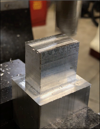
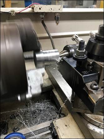
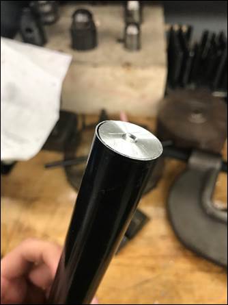
The filler piece was
machined using the lathe. Since it had been a while since the team had worked
with a lathe, we were guided by one of the machine shop assistants. Once we had
gotten refamiliarized with the lathe, we machined the filler to spec. The
filler piece had to be smaller in size to fit inside the hollow steel tube
(flagpole). The filler is 0.94 inches in diameter and 1.25 inches in length. Once
the filler material was reduced to its proper size, we pressed it inside the
top end of the first flagpole section (snug fit). Again, this will serve as
additional material for the bolts that will run through the flagpole section to
hang onto. Without the filler, the bolts would only be grabbing on to the outer
(thin) walls of the pole, which won't be very secure (creates stress
concentration).
|
|
|
|
Figure 62 - Using Lathe
to Machine Filler |
Figure 63 - Filler
Inside Pole |
|
|
|
|
Figure 64 - Pole with
Filler inside Connector |
Figure 65 - Drilling
Holes inside Connector |
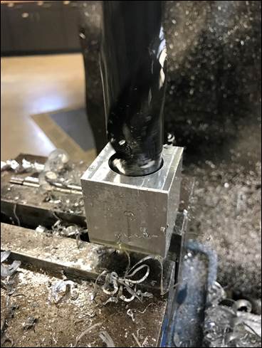
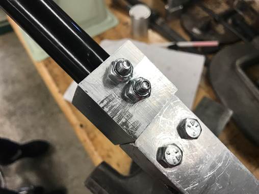
The team then inserted
the pole (with the filler) inside the connector and drilled two 1/4"
holes. Two bolts will be used to secure the pole (together with the filler) to
the connector piece. The pole-connector sub-assembly was then attached to the
hook frame using two bolts. Once secured, the device gained the additional
function of being able to attach and remove pole sections. Although this new
design is similar to the previous one, we believe this
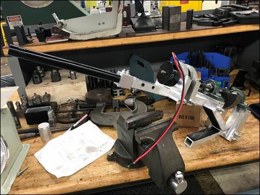
connection will be much stronger and sturdier. The two figures below depict the
harvester after it had been fully repaired. Now that the device was completely
repaired, field testing could resume.
|
|
|
|
Figure 66 - Connector
attached to Pole and Hook |
Figure 67 - Completed
Repair of Harvester |
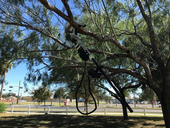
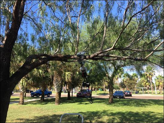
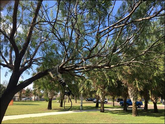
Field Tests at Park (Repaired Hook)
After repairing the hook, we visited Zinnia Park a couple of times
to test our new, fixed prototype. Our first visit consisted of mostly
observational data; recording which frequencies excited the mesquite beans the
most. This gave us an idea of what range of frequencies worked best. On our
next visit, we used an accelerometer phone app to measure the acceleration experienced
by the branches. The acceleration data obtained was then used to estimate the
forces experienced by the branch during operation. This set of experiments are
critical to evaluating the performance of the harvester.
Here is an
outline of the experiments we carried out:
First, we had the assembly all attached together, with the
polycarbonate casing and the fixed pole connection (1st section). Then,
we attached the hook frame around the first branch. For the lower
branches, we just left it there with the default 1st stainless steel
pole section attached to the frame. For the longer branches
we attached the other sections by screwing them from the 1st one, depending on
how elevated the branch was from the ground. The ability to attach and remove
sections of the pole prevented the pole from reaching its natural frequency
during testing. This is a clear improvement over the 1st design which
prevents the pole from failing in the same manner. While the prototype was
running, we had someone designated to monitor, and lightly touch, the base of
the lowest pole extension section, in order to prevent
any possibly tipping over of the hook from the branch. The main difference in operating the device from the 1st field
test is that now the speed could be controlled from a short distance away. The
speed controller was connected to the hook via the umbilical cord. This made it
easier to control because the dial would not shake with the hook. It is
also safer for the user. We tested at varying branches
at a steady sweep of frequencies. We
went at intervals of increasing the percent power 5 percent each time, closely
observing the movement of the branches.
|
|
|
Figure 68 - Hook
Ganging on Branch |
|
|
|
|
Figure 69 - Harvester
Shaking Branch |
Figure 70 - Controlling
Device from a Distance |
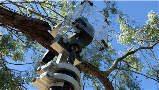
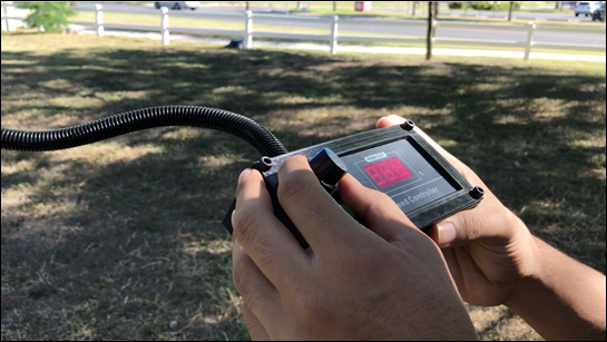
Table 1 - Optimal Frequencies for
Branch Displacement by Observation
|
Branch |
Circumference (in.) |
Diameter (in.) |
Length (in.) |
Voltage Range (% Power) |
Frequency (Hz) |
|
1 |
8 |
2.546 |
110 |
50-55 |
8.253 |
|
2 |
9.25 |
2.944 |
150 |
45-55 |
7.37 |
|
3 |
7.875 |
2.507 |
107 |
30-40 |
3.95-5.576 |
|
4 |
6.25 |
1.989 |
75 |
30-40 |
3.95-5.576 |
|
5 |
10.75 |
3.422 |
90 |
32-35 |
4.6-5.576 |
CHECK OUT our Repair Process and Field Testing.
See Video Below!
|
|
|
|
Figure 71 - Experimental Set Up 1
(Hook at Angle) |
Figure 72 - Experimental Set Up 3
(Phone Closer to Beans) |
Eventually, we got to our final experiment, where
we were able to obtain more concrete, quantitative data (rather than just
eyeballing the results). We did this using an
accelerometer app on a phone that would be able to display real-time
graphical results of the x-, y-, and z-displacements of the phone. For each branch that we wanted to test, we taped the
phone, with the app ready to run at the outer reaches of the branch. Before running each test, we measured the approximate
circumference of the branch near the taped region and the horizontal distance
from the hook's grip to the phone's location. We then ran the test starting at 30 percent power
(with the phone accelerometer also being active at this time), let it run for
15 seconds, then stopped the prototype and stopped the measurements the
phone took. The data was
then exported, and we prepared to increase the percentage
power for the next run. For the
next run, we went up by 5 percent and then repeated the process that was
done for the first run; this went on for several steps.
|
|
|
Figure 73 -
Steady-State Force Amplitude v. Voltage % Plot |
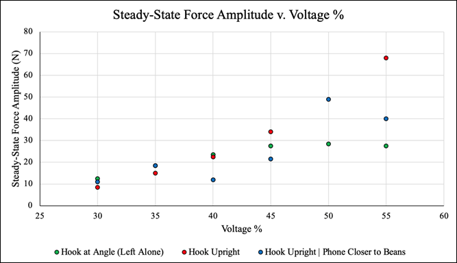
The results of the second
field test are summarized in the graph above. It is shown that
as the voltage percentage increases while operating the device
with the hook upright, the steady-state force amplitude increases linearly. The
same is not true for when the device is closer to the beans, as the
amplitude seems to fluctuate as voltage increases. Furthermore, in both cases,
the upright hook produces a greater amplitude than the angled hook at
higher voltages.
Although this set of data does not give us a
direct answer regarding the effectiveness of the device, we believe a
correlation can be made between the acceleration and the displacement of the
branches. This relationship should result in a more accurate way of evaluating
the device's performance. Still, we believe the experiments conducted helped us
understand what range of frequencies and position of the harvester are ideal.
FINAL PRODUCT
After much work, this is our final
product.
|
|
|
Figure 74 - Mechanical Mesquite
Bean Harvester |
|
|
|
Figure 75 - Mechanical Mesquite
Bean Harvester Model |
Pictured above is our final
SolidWorks model. This model includes some our latest design changes (connector,
filling, steel flagpole) as well as other components not previously included
(battery case, shaft collars, bolts, nuts). The team believes having a detailed
model of the device is very important. It allows us to demonstrate what
components make up the device and how each component works together to function
as one.
The following figure shows the
different components of the device.
|
|
|
Figure
76 - Mechanical Mesquite Bean Harvester Model (Side View) |
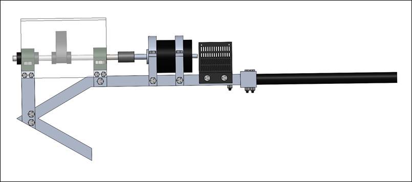
By creating a detailed SolidWorks
model of the Hook Assembly, the team was able to put together an assembly
manual that shows the user how to assemble the device step-by-step. This will
help guide the user throughout the assembly process and prevent any mistakes
from being made. In addition, this manual will reduce the time needed to assemble
the device. The assembly manual includes pictures of each step as well as lists
the components involved for each step. We also made an assembly video and a
written instruction manual to help aid the assembly process. The team believes the
combination of these three guides are important for the user to assemble the
device correctly.
Click HERE to view Assembly Manual.
Click HERE to view Written Instruction Manual.
CHECK OUT our Assembly Guide Video Below!
The team also made a simple rendered
animation of the Mechanical Mesquite Bean Harvester using Blender. The model
shown in the video below is based off the SolidWorks model. The model was
imported to Blender as an STL file, after which minor modifications were made
(added materials, lighting). The animation is a simple revolve around the
Mesquite Harvester. This animation allows the team to showcase an accurate
model of the device.
CHECK OUT our Mechanical Mesquite Bean
Harvester Animation Below!
Our project is a proof of concept
that requires further development. The team has laid out a plan regarding what
we believe should be done next to improve the device. These are some of the
pending items as well as things we think should be done differently:
o
Testing during
the mesquite bean harvesting season (May - August). While our device works as
intended, we would have liked to test it on mesquite trees that have ripe beans.
o
Implement new
battery-charging method. The current process involves
having to untie the battery wires and charging them separately. This is a long process considering the wires need to be
removed from the umbilical cord, which takes a while. We would have preferred
using a battery which could be easily charged without needing to disassemble a
portion of the wire tubing. The team believes replacing the battery pack with a
rechargeable internal battery, like the kind of rechargeable battery found in a
cell phone or laptop, would work better.
o
Try new methods
to excite mesquite beans. Perhaps a more direct approach to
harvesting mesquite beans would work better. Our
approach was to excite/harvest as many mesquite beans at once by transmitting
vibrations through the branches. However, there may be a more efficient and
productive way of harvesting mesquite beans by simply "raking" them
off the branches.
o
Try and see if
a wireless connection for controlling the volt percentage power could be
feasible. Wireless control would allow the user to
control the device from a safe distance away.
o
Possibly try
out a grip attached to a long, tensile cable that could possibly transmit
vibrations. This way of harvesting would involve a
tractor and some sort of attachment.
o
Use cameras
(slow-motion) to record motion of mesquite beans and come up
with amplitude-frequency response graph that estimates the natural
frequency of mesquite beans. Since the whole idea is to harvest mesquite beans,
it is best that we look carefully at how the mesquite beans respond to the
excitation induced (Do not rely too much on simple observation).
o
Reduce as much
weight as possible from harvester to allow for easier handling. Currently, the
harvester weighs just over 20 pounds. Making it lighter will make it easier to
carry around during harvesting.
o Since
everything in nature is nonlinear and mesquite trees are a very complex system,
the team believes a variety of frequencies may be used to cause mesquite beans
to reach their natural frequency. There is no one correct frequency to be
applied to every mesquite tree branch. Because the geometric and mechanical properties
of each mesquite branch is different, it affects how the beans respond to the
vibrations transmitted.
IN CONCLUSION
Our Senior Design experience:
Throughout Senior Design, the team
enjoyed collaborating with one another and working together to create a working
prototype. Our Senior Design project focused on developing an efficient harvesting technique
that will expedite the mesquite bean harvesting process and thus help
farmers/ranchers increase their mesquite bean yield and supply of mesquite bean
products. Although the device was not as effective at harvesting mesquite
beans as we'd hope, we believe the development of the mechanical mesquite bean
harvester is a critical step to creating an improved model. While further
testing of the device will need to be conducted to accurately assess its performance,
the team has helped pave the way towards solving the task at hand. We believe our
device will prove to be helpful in improving the efficiency of the mesquite
bean harvesting process, and with some more work, will ultimately aid farmers
by allowing them to harvest mesquite beans with greater efficiency than
hand-picking.
In
addition, working on this project was a valuable educational experience for us.
It gave us a lot of useful experience, such as hands-on machining and
troubleshooting, that will help us in our future engineering careers. This
project is an interesting bridge between the engineering and agricultural
disciplines. Getting the opportunity to work with the Cappadona family was a huge pleasure. The team learned
a lot about the importance of mesquite trees and mesquite beans. Moreover, we realized
the impact a mechanical harvester can have on the mesquite bean business. A
mesquite harvesting device will fundamentally change how the mesquite tree is
viewed and used. Knowledge of subjects outside of college engineering courses
is helpful. In the real world, most engineering problems are not covered in
college courses, and require a level of engineering experience and judgement to
solve. The mesquite harvester is a good example of this type of problem. The
experience gained while working on this project cannot be replaced by a typical
engineering course.
The team considers this a very important problem
that we as engineers can help solve. We strongly believe this
project can continue to progress and improve based on our work.

REFERENCES
[1] Ramos, Mary. "The Ubiquitous
Mesquite, " Texas Almanac, Texas State Historical Association
(TSHA), 2007, https://texasalmanac.com/topics/environment/ubiquitous-mesquite
[2] "Plant Database - Prosopis glandulosa, " Lady
Bird Johnson Wildflower Center, 6 November 2015, https://www.wildflower.org/plants/result.php?id_plant=prgl2
[3] "The Amazing Mesquite Tree, " Cappadona Ranch, 7 March 2017, https://cappadonaranch.com/blogs/blogs/the-amazing-mesquite-tree
[4] "Mesquite - The Wonder Tree, " An Eye
for Texas, 29 March 2011, https://aneyefortexas.wordpress.com/2011/03/29/mesquite-the-wonder-tree/
[5] DuHamel, J. "Mesquite
Trees provide Food, Fuel, Medicine, & More, " Arizona
Daily Independent News Network, 7 July 2013, https://arizonadailyindependent.com/2013/07/07/mesquite-trees-provide-food-fuel-medicine-and-more/
[6] "Rotating Unbalance, " Virtual Labs -
An MHRD Govt of India Initiative, http://mdmv-nitk.vlabs.ac.in/exp6/index.html
[7] Niklas, K.J., 1992, Plant
Biomechanics - An Engineering Approach to Plant Form and Function, The
University of Chicago Press.
[8] James, K.R., Dahle, G.A., Grabosky, J., Kane, B., Detter,
A., 2014, Tree Biomechanics Literature Review: Dynamics, Arboriculture &
Urban Forestry 40(1), 1-15.
[9] Dargahi, M., Newson, T., Moore,
J.R., 2020, A Numerical Approach to Estimate Natural Frequency of Trees with
Variable Properties, MDPI Forests 11, 1-21.
[10] 2010, Frequency Response of Trees, Dept. of Civil and
Environmental Engineering MIT, 1-31.
[11] Baker, C.J., 1997, Measurements of the Natural Frequencies of
Trees, Journal of Experimental Botany 48(310), 1125-1132.
[12] Ganji, H.D., Ganji,
S.S., Ganji, D.D., Vaseghi,
F., 2011, Analysis of Nonlinear Structural Dynamics and Resonance in Trees, Shock
and Vibration 19, 609-617.
[13] Loghavi, M., Khorsandi,
F., Souri, S., 2011, The Effects of Shaking Frequency
and Amplitude on Vibratory Harvesting of Almond, ASABE.
[14] Ni, H., Zhang, J., Zhao, N., Wang, C., Lv,
S., Ren, F., Wang, X., 2019, Design on the Winter Jujubes Harvesting and
Sorting Device, MDPI Applied Sciences 9, 1-17.
[15] James, K.R., Haritos, N., Ades, P.K., 2006, Mechanical
Stability of Trees under Dynamic Loads, American Journal of Botany 93(10),
1522-1530.
[16] Polat, R., Gezer, I., Guner, M., Dursun, E., Erdogan,
D., Bilim, H.C., 2006, Mechanical Harvesting of
Pistachio Nuts, Journal of Food Engineering 79, 1131-1135.
We went through a meticulous design
process to arrive to the final solution. The information in this page is a
summary intended for the general public.
To learn about the project details, visit the DESIGN PROCESS Page.
To
obtain access Click HERE.
We would like to recognize and
thank several people whose help was critical to the team's success.
Dr. Noe Vargas (Senior Design
II Professor) - Guided team
throughout Senior Design, gave us advice on several different aspects of the
project, and provided us access to the Makerspace during the build stage.
Dr. Arturo Fuentes (Faculty
Advisor) - Regular feedback
and engineering advice regarding mesquite harvester. Constant support
throughout the project. Always gave us his thoughts on our proposed ideas and
suggested we try different methods to excite the mesquite beans.
Dr. Joanne Rampersad-Ammons
(Faculty Advisor) - Regular feedback
and information regarding mesquite harvester. Helped us understand the importance of
this project and the impact it can have.
Mr. Gregory Potter (Senior
Design II Assistant Professor) -
Advice for improving prototype.
Mr. Hector Arteaga (Machine
Shop Technician) - Machine shop
training and general help throughout
manufacturing process. Gave us his thoughts regarding different ways to
manufacture certain components. Helped the team a lot during build stage and
got the team involved with machining.
Mr. Jose Sanchez (Mechanical
Engineering Professor) - TIG
welded aluminum hook for the team.
Cappadona Family - Helped team by showing us the mesquite bean harvesting
process and how they process the beans to make different products. Showed us
around their ranch and allowed us to test our device there. We had lots of fun
and learned a lot from them.