Concept Variants
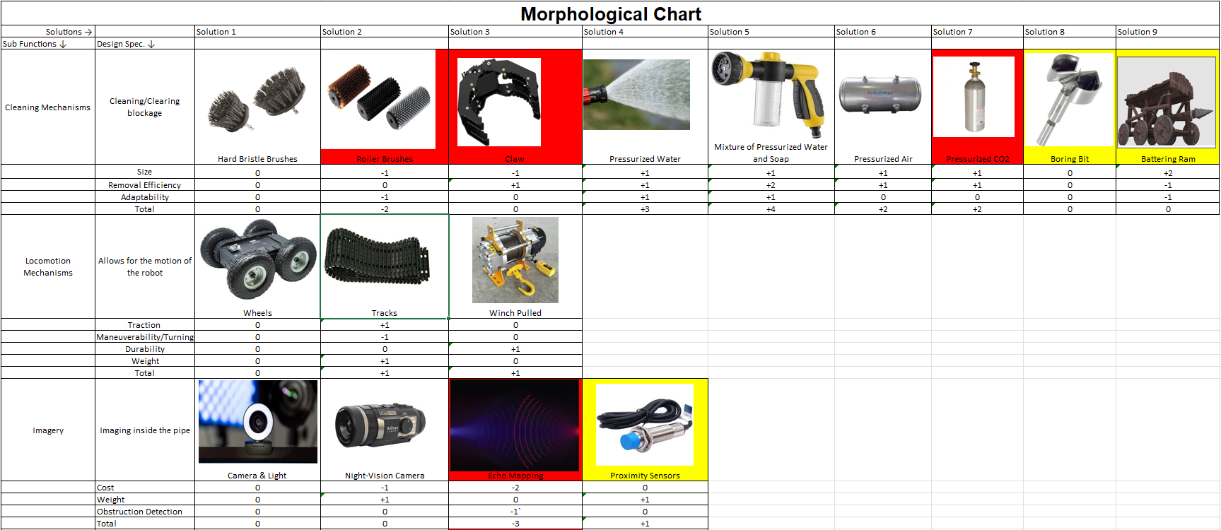
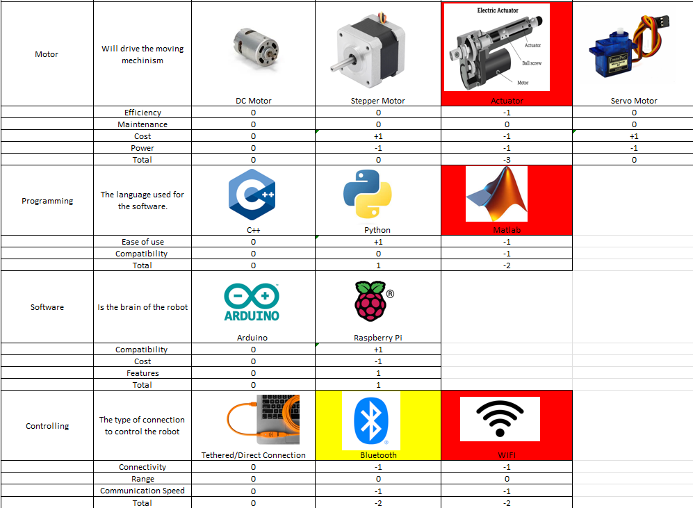
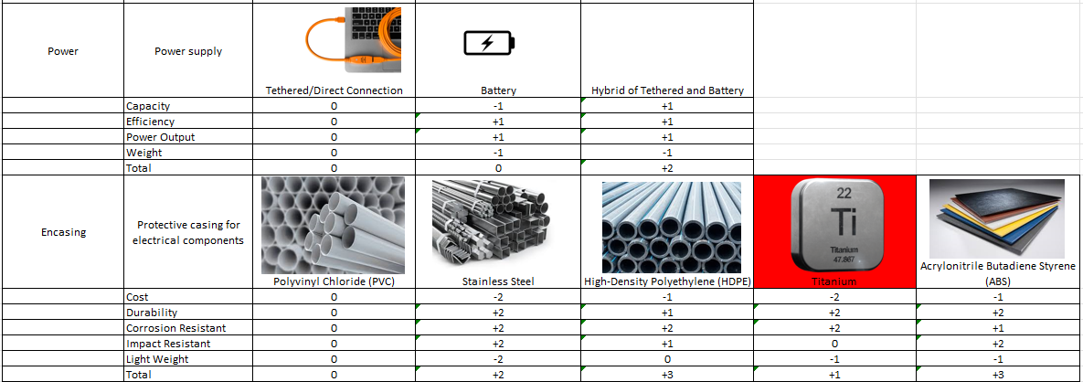
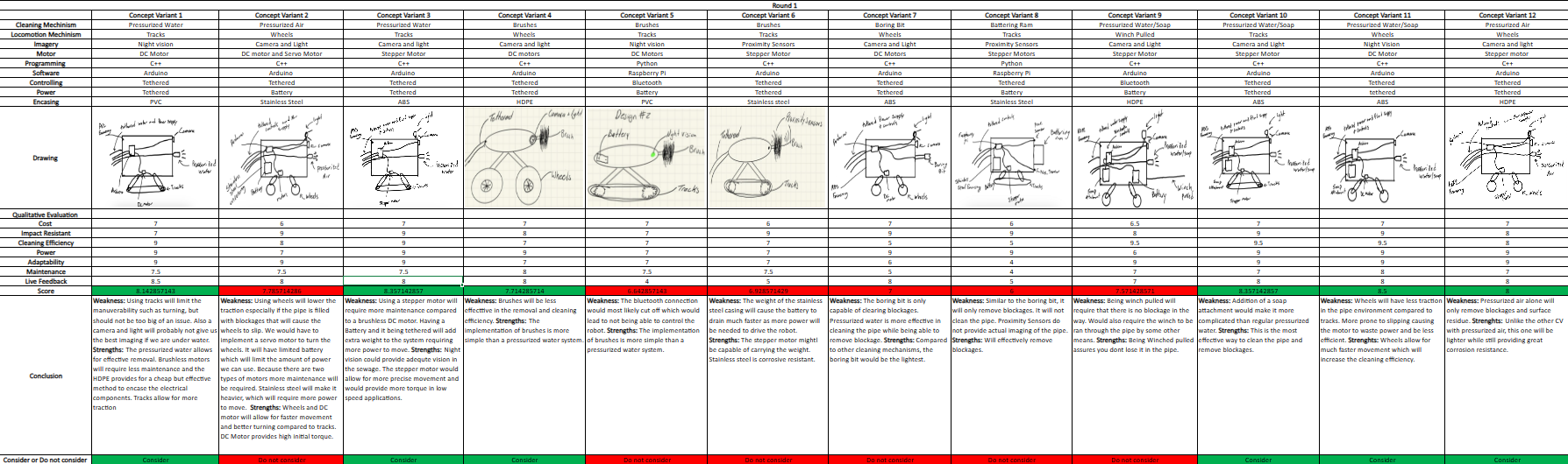
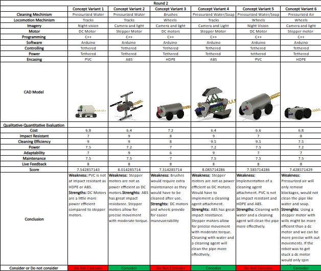
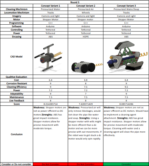
The following charts are the 3 rounds that our group performed for the concept variants of which the previous CAD model came out as the favorite. The first round consisted of a total of 12 different variants, each with their own unique combination of parts. In this round, we had simple sketches for each variant so we could have an idea of what it would turn out to be. They each had pros and cons, but ultimately, only 6 were chosen to move on to the second round. In the second round, all of the 6 variants had a 3D CAD model of them made so that we could better understand what we would need for each variant to operate effectlively. Finally, of the 6 that moved on from the previous round, only 3 moved on to the final one. For the 3rd round, we compared each of the 3 variants with each other and selected what we thought was the best one.
Design
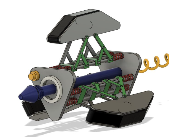
When it came to the design of the prototypes, we wanted something that would be able to traverse the pipes without to much trouble and be able to fit different pipe diameters. Since we already had an idea of what we needed and what we wanted, we came up with what we thought was a good solution for both. This design is our CAD model that made it through all the concept variant rounds and it still had to go through more iterations before we were satisfied with the design.
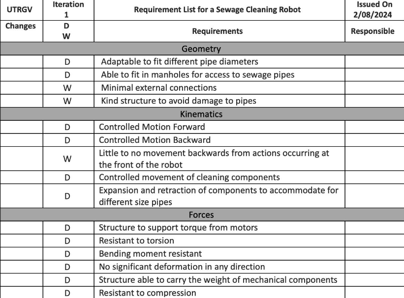
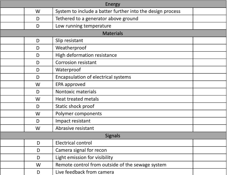
Design Specifications
The design specifications for our robot are specifically what we need our robot to be able to do. This includes but is not limited to making the size adaptable so it can fit into different pipe diameters, controlling the movement of the cleaning components, and making the body impact resistant.
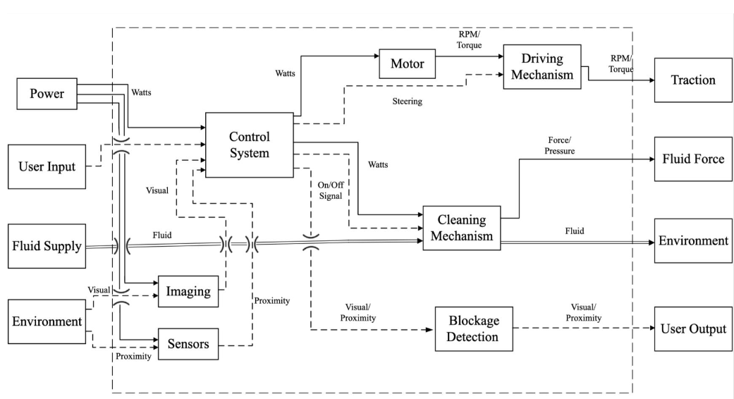
Functional Diagram
The functional diagram for our robot looks as follows:
Embodiment Design
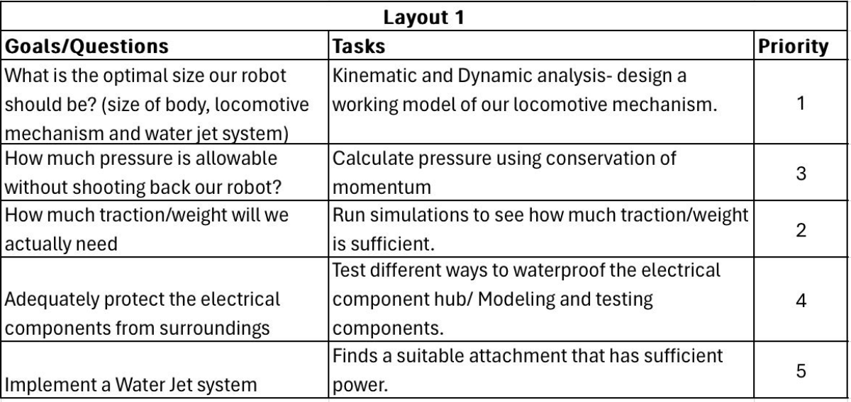
The goals and questions that we asked ourselves were simple. We wanted to know the optimal size of our robot, how much pressure was allowable without pushing the robot back, how much traction we would need, how to protect the electrical components, and to implement the water jet system. These goals and questions are then assigned tasks and ranked in order of priority.
FMEA
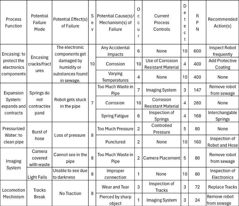
The failure mode and effects analysis is a very important part of our designing process. The FMEA, for short, is a graph that shows some of our process functions and how they can fail, their severity, and what can be done to prevent this from happening. This helps us visualize what can go wrong so we can be better prepared for any mishaps.
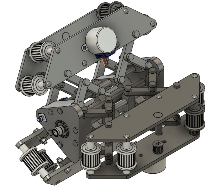
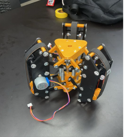
Current Model
This model is a more refined version of the model that made it through the concept variants. This specific 3D model has arduino stepper motors, tracks and belts, and is took tolerances into account. It also has aluminum guide rods for rigidity and is made of PLA material. This model serves as our proof of concept.