UTRGV
/ COLLEGE
OF ENGINEERING AND COMPUTER SCIENCE / MECHANICAL
ENGINEERING DEPARTMENT
(Index
Page: General Audience)

|
SDI Students (L-R) |
·
Israel Falcon ·
Alejandro Garcia · Sabrina Dougherty · Jacob Gil |
|
Faculty Advisor(s) |
· Dr. Joanne Rampersad-Ammons · Dr. Horacio Vasquez |
|
Course Instructors |
· Dr. Noe Vargas Hernandez · Mr. Greg Potter |
|
College of Business and Entrepreneurship Collaboration |
Dr. Sylvia Robles (Instructor) ·
Andy Garcia ·
Nicolas Perez ·
Matthew Woodlee ·
Sarah Loya |
WHAT
IS THE PROBLEM WE ARE TRYING TO SOLVE?
WHY
IS THIS PROBLEM IMPORTANT?
LEARN
MORE ABOUT OUR DESIGN PROCESS
Welcome! We are team #7 “007”. We are Sabrina Dougherty, Israel Falcon, Alejandro Garcia, Jacob Gil, and Reyes Mendoza. We have been working on this project for the entire Spring 2021 semester, and we will continue to work on it on the Fall 2021 semester. Our project is titled “The Bee Project,” and the problem we are tackling is the low number of apiaries in the RGV region due to lack of interest and the difficulty of getting started in beekeeping. We have designed a device that allows aspiring beekeepers to get started in this activity by monitoring the weight of their beehive. Important information can be gathered from the weight of a beehive such as when the honey produced in their hive is ready to be harvested. We hope you enjoy this project as much as we have enjoyed working on it. Index Welcome Movie

In about
30 years our population will increase by 30%. There will be a greater need for
more food to feed everyone, and the current farmers are an older generation
that will not be active during that time. Further, the younger generation is not
becoming as involved in farming to balance the decline. In the RGV, beekeeping is a farming
activity that needs to be further developed to increase the bee population in
the region. Currently, the number of bee farms
in the area is substantially low in comparison to the future growth in
population due to the lack of people getting involved in this activity. In
order to foment upcoming bee farming, we are seeking to develop a product that
enables people without experience in this activity to obtain an easy-to-use
solution that can get them started in bee keeping.

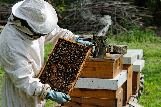
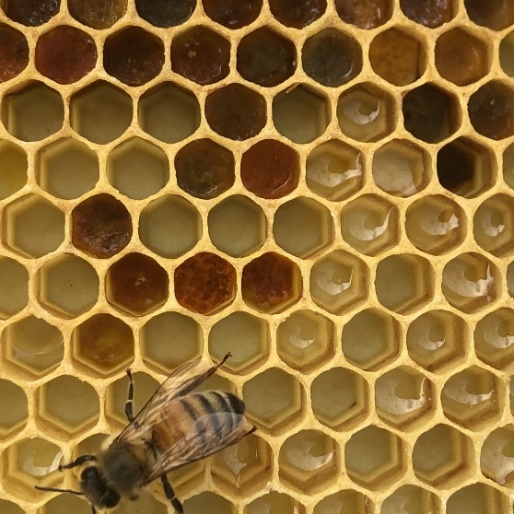

Figure 1. - A depiction of a
beekeeper and the type of beehive used for our project.
To better understand the problem, we
have been conducting background research on the topic, and from this background
we have learned the following:
· Bees present a complex behavior which
must be acknowledged by the beekeepers for them to efficiently interact with
the bees. Bees have a well-defined and structured society based on work and
protection of their queen.
· Knowing the weight of a beehive can
reveal vital information regarding the overall state of the honey being
produced and the bees inside the beehive.
· Different components that interact
with the beehive, such as the bees, honey, and external factors affect the
total weight of the beehive, which can amount to a total of around 300 lbs in
some cases.
· Current beehives in use include the
Langstroth beehive, which is a customizable design made up of 8 to 10 frames and
are (mainly) made of wood. These are the most used beehives in North America.
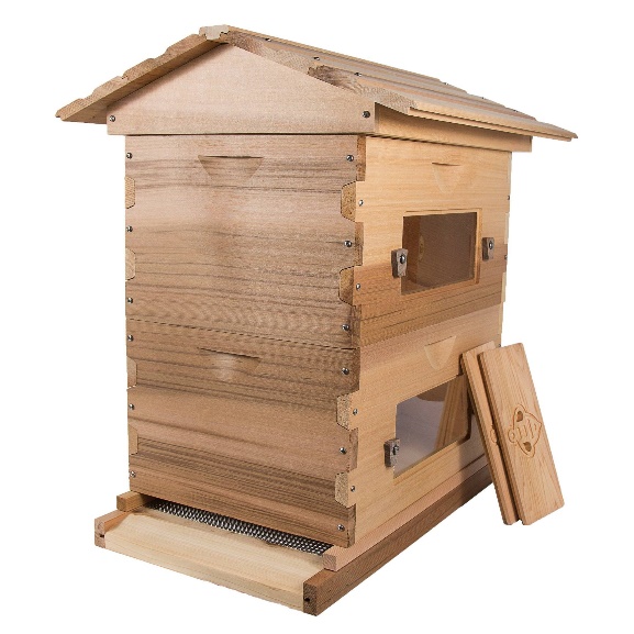
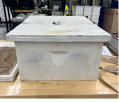
Figure 2. - Two displays of the Langstroth
beehive
· Currently, bee farming depends mainly
on the experience of the beekeepers since there are not many commercially
available resources that aid the process.
· Due to the weight of the beehive, the
most non-invasive & efficient way to weigh the beehives is by resting them
on top of a device that is similar to a floor scale.
· Regulations in the United States
regarding bee farming is mainly focused on the interstate commerce of bees to
prevent the introduction of certain species into environments where they should
not be.
· Animal rights activist groups advocate
for the ethical treatment of bees in bee farming; therefore, our device must
not interfere substantially with bees and their immediate environment.
· Load cells are force transducers that
convert the force exerted on them into electrical signals. These devices are
the ones responsible for providing weight measurement readings caused by the compression
experienced on the base of the scale by being in contact with the beehive.
There is a great variety of load cells that serve different purposes depending
on specific conditions under which they operate.
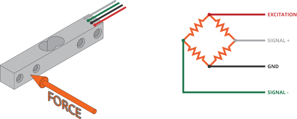
Figure 3. - A single point load cell and
a simple model of the electrical circuit
· The use of a corrugated structure provides
an efficient alternative to reduce the amount of material used in the
development of our device while giving it a stable platform.
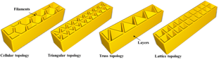
Figure 4. - Four different styles of
corrugating/infill structures
· Current solutions similar to our
product include the “Solution Bee”, which is a device that collects information
such as the weight and temperature in the beehive and stores it for monitoring
of the beehive.
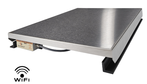
Figure 5. - Solution Bee’s product
· Another solution to the problem is a project
known as “Weight my Bees,” which is a similar idea to both “Solution Bee” and
our product. However, this is not commercially available since it is used in
research to aid in finding a solution to the Colony Collapse Disorder.
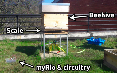
Figure 6. - A Senior Design project
similar to our solution
Our main motivation to work on this
bee farming project is the environmental impact embedded in the problem we are striking.
We believe that the potential negative impacts generated by the decrease in bee
population and bee farming could be detrimental to society, not only in the RGV
region, but it could also influence the entire population. The complexity of
this problem is not only embedded in the environmental effects it generates,
but it also poses economic problems and potentially social injustice in the
disparity of food distribution to certain vulnerable communities.
Several aspects of life are affected
by this issue, which is why there is a great variety of stakeholders in this
project. A graphical depiction of some of these is present in the Stakeholders’
Map below.
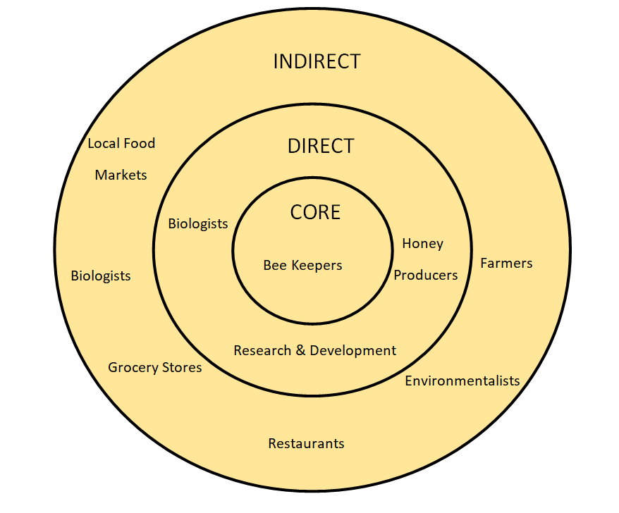
Figure 7. - Above is our
Stakeholders’ Map representing the different groups of people affected by the
problem we are trying to solve
“What we offer when compared
to our competitors is an easy and affordable way to start or continue
beekeeping. By providing a user-friendly and inexpensive product to help people
access vital information of their hives, this should incite their interest in
beekeeping.”
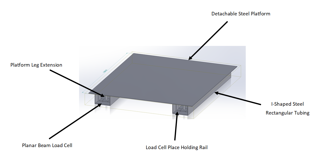
Figure 8. - Above is the original design of the beehive
scale
After understanding the problem in
depth, we explored various potential solutions and selected the best concept
(Pahl and Beitz, 1996).
Our product solution works by
utilizing the essential concepts behind a regular scale with certain
modifications that consider the specific needs of our problem. We have
developed a scale-type device that works alongside components such as a
Bluetooth module that allows the user to gain access to the weight measurements
of their beehive. Our device is powered by a rechargeable battery which allows
it to operate constantly and provide real time data to the user.
With the expected range of the beehive is between 300-500 pounds, a secure design is needed to ensure stability is achieved. Although several design concepts and bases were considered, a steel “I” rectangular tubing base with a top thin platform was selected.
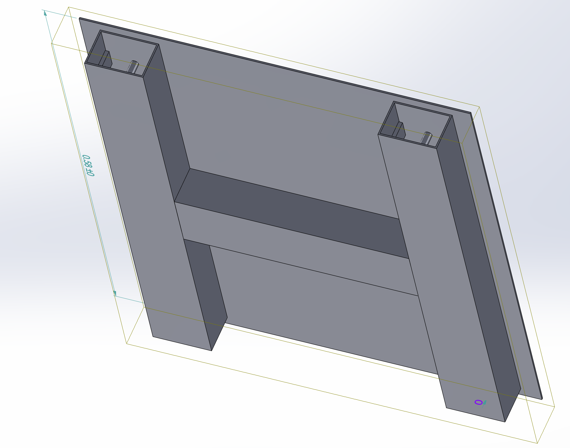
Figure 9. - Above is an isometric view
of the original design
The weight measurement readings are
obtained using load cells. Several load cells are installed inside the
rectangular tubing, and these capture the weight from the platform and the
beehive on top of it. Additionally, the data collected by the different load
cells is summed up with the amplifier.
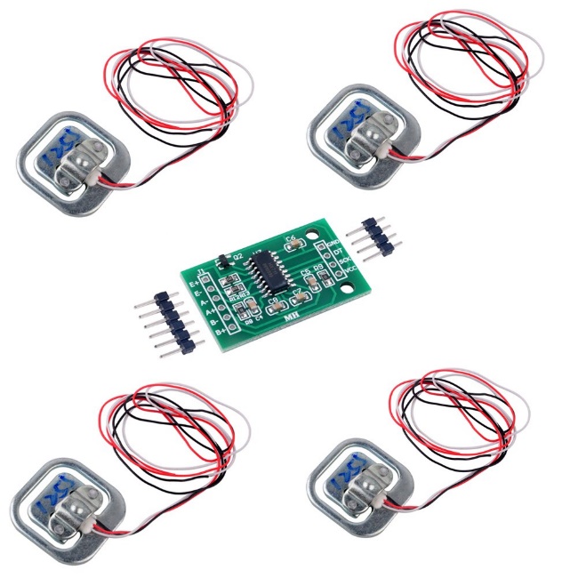
Figure 10. Load cells and an HX711 amplifier
are shown above
In order to ensure that the complete weight of
the beehive is directly on the loadcell, the platform can’t rest on the
rectangular tubing of the scale. If the platform is resting on the tubing, the
weight of the beehive would be distributed across the platform and tubing,
which would result in an inaccurate reading. To tackle this issue, the platform
will be “floating” on top of the tubing by having “legs” that will rest
directly on the load cells.
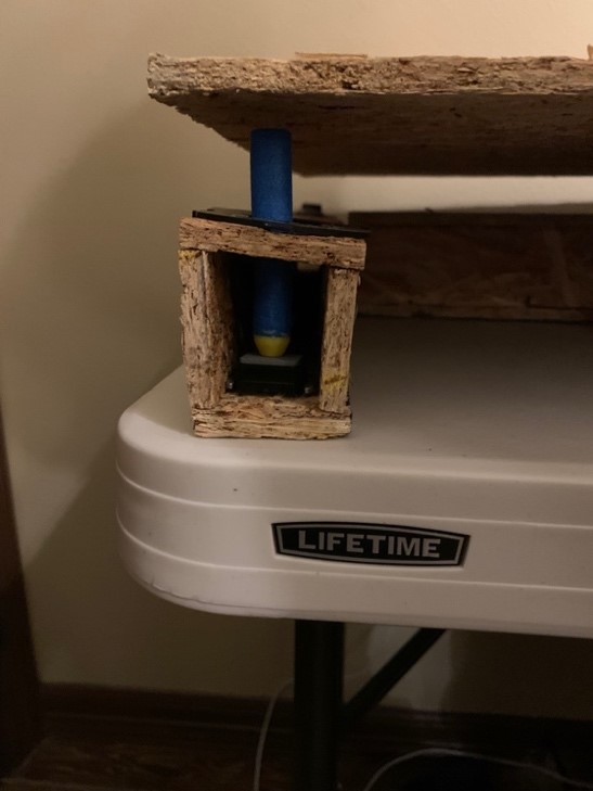
Figure 11. Early prototype showing
how the plate will rest on a pin that will directly hit the load cell
A Bluetooth module, amplifier, and a display
screen will be attached to an Arduino. The Arduino will receive the summed data
from the amplifier and send the information to the cellphone of the user and to
the display screen. This allows the user to receive the weight readings of
their beehive by looking directly at the display screen or through the data
sent directly to their phone.
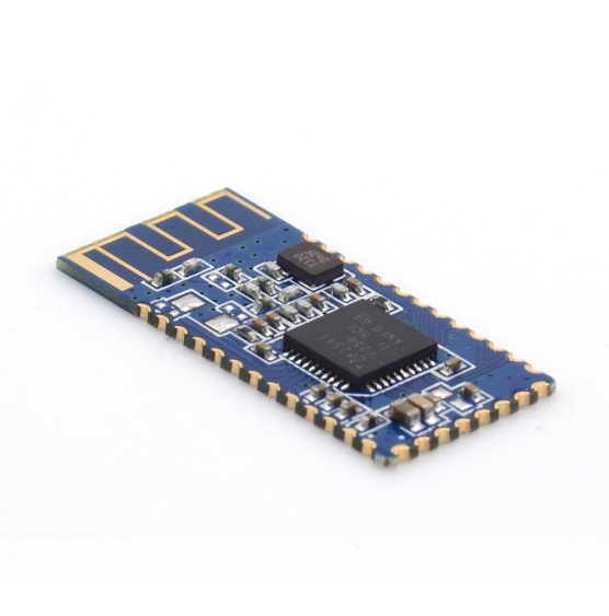
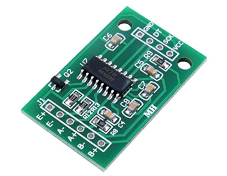
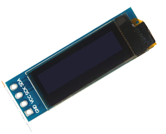
Figure 12. The Bluetooth
module, amplifier, and display screen are shown above, respectively
Once we defined a clear solution idea
(i.e., concept), we applied our engineering knowledge to transform it into a
real product. These were some of the important design challenges and how we
approached each one of them:
·
Platform of device must not be directly attached to the base
To ensure the device provides accurate weight readings to the user, the load cell must receive the entirety of the load. Having the platform attached to the base would dissipate the load carried by the platform onto the base. Therefore, the load cells would receive an inaccurate reading. A platform that would not rest on the rectangular base is needed. A solution to this challenge would require the design to have a platform with “legs” (pins) that will connect to the load cells to remain lifted off the base.
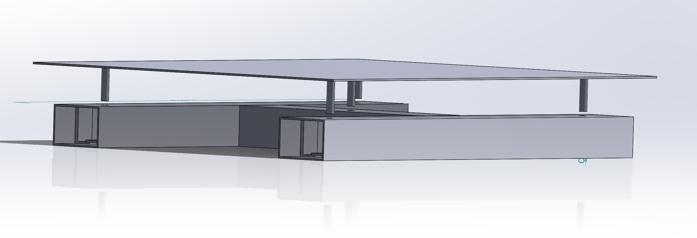
Figure 13. The top sheet would be a
removable piece that remains lifted on the tubing due to the pins resting on
the load cells
·
Implementation of additional load cells must consider deflection of the
platform
By testing our
prototypes, we recognized how the platform would deflect significantly in the
center. The beam that connects both sides of the base does provide enough
stability for the base to not fail; however, the deflection cause the platform
to be in conduct with the middle beam. Since this would prevent the load cells
from all the load, an additional load cell was implemented in the middle beam.
This would allow for the load to be distributed through the five load cells
without touching the rectangular base.
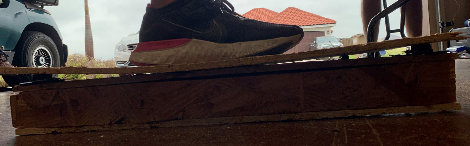
Figure 14. This early prototype shows
how the plate deflects in the center
·
Middle beam must have a door to access inside components
To provide
the user with a device that is easily repairable, we are attempting to make all
parts of the device replaceable and easily accessible. Therefore, since the
middle beam will have multiple components inside it, we must incorporate the
use of a door on the side of the beam to allow for easy access to the inside of
the beam.
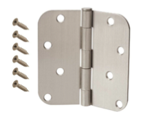
Figure 15. The team considered
implementing a hinge to have a door for replaceable components such as a
battery
·
Load cell
placement position on rectangular tubing
The team faced
much difficulty about where to place the load cells. The middle of the load
cell holds the strain gauge, which measures the displacement of the center
section as it is pushed down while the outside section remains on a flat
surface. Little to no movement of the entire load cell is necessary to ensure
that the best accuracy is achieved. Therefore, scenarios involving the load
cell inside and outside of the rectangular base were considered and tested.
With the load cells outside and on top of the rectangular base, concerns arose over
how to prevent the outside weather and animals (bees) impact the load cell. With
the load cells inside the rectangular base, it allows them to be protected well.
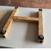

Figure 16. Both
scenarios with the load cell on top and inside of the base were tested with
multiple prototypes
·
Development of leg extension for platform to be in direct contact with
load cells
The accuracy
of the readings obtained from the load cells depends greatly on the fact that
the load desired to be measured sits directly on the load cell so that none of
its weight can be distributed among other components of the device. Therefore,
the need to develop an extension to the platform so that it touches the load
cells exclusively is imperative. This presents a challenge in the manufacturing
of such extension to the platform due to the dimensions and shape of the load
cells. Certain structural alterations such as an indentation or a tap thread on
top of the load cell must be made in order to secure that the leg extension and
the load cells remain in contact permanently.
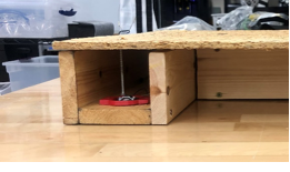
Figure 17. Above
shows how the leg, which a screw for this prototype, is resting directly on the
load cell
We found that physical prototyping
was very helpful to increase our understanding of the problem and the
feasibility of our solutions. Our first prototypes were simple but useful and
we continued evolving into more complex ones.
This was our first prototype, it may
be simple, but it helped us understand how the architectural design of our
device must be for it to be able to withstand the load of the beehive. This
first prototype allowed us to get an idea of the dimensions and ratios required
for the parts in our actual product. This early prototype helped us acknowledge
that the structural design of our product is of vital importance since it was
able to withstand a weight of almost 180 lbs. even though the prototype was made
of cardboard and assembled with duct tape.

Figure 18. First prototype
This was our second prototype, which
was made of compressed wood, and in comparison, with our earliest prototype it
was more complex. For this second prototype we used nails to assemble all the
parts together and we used a 1:1 scale compared to our final concept design. This
second prototype enabled us to realize that the platform in our device will
deflect due to the high loads it will be subject to.
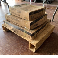
Figure 19. Second Prototype with multiple
weights resting on top
Our third prototype was made of the
same material as the second prototype, but more care was taken in cutting and assembling
the scale with different dimensions and ratios. Here, we placed the load cells on
top of the base but below the platform and tested it by adding weight on top of
the platform. However, it was concluded that this setup would not be ideal for
several reasons. Applying weight onto the scale showed us that we needed to
modify the amount of load cells by adding one directly in the center of the
middle beam. Another reason is that the load cells would be placed in a
position in which they would be exposed to interactions with bees and other
external agents that may alter the integrity of the load cells and thus cause
significant alterations to the device. Additionally, it was concluded that the
setup would be difficult to manufacture. The placement of the load cells at the
top of the square tubing would require the use of welding to keep the load
cells in place and the contact area between the welded edge on which the load
cell would rest is relatively small. Therefore, it might not be able to withstand
the load of the platform and beehive.
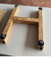

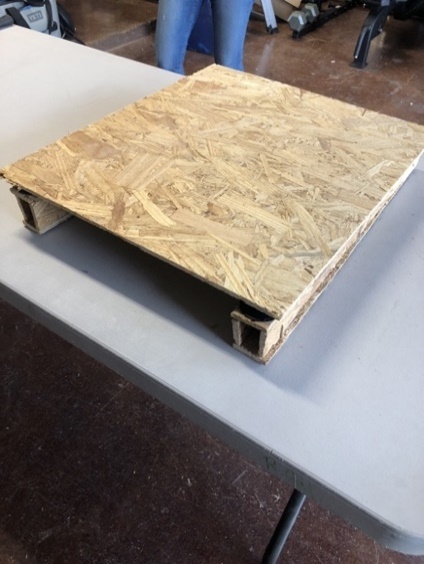
Figure 20. Multiple views of the
third prototype with and without the top sheet
Our fourth prototype is the exact
model we used for the third; however, the difference lies in the placement of
the load cell. We felt securing the load
cells inside the metal tubing was the best option for maintaining safety and maximizing
accuracy of the load cell. Because the platform was no longer going to be in
direct contact with the sensor, a new design had to be created. We decided to
utilize a screw that would be screwed on through the platform and through a
hole on the top surface of the base directly above the load cell. As weight is
applied to the platform, the screw would press down onto a threaded tap located
in the center section of the load cell. This design allows for easy
installation and detachment of the top platform and should evenly distribute
the applied load to all the sensors within the rectangular tubing.


Figure 21. Multiple views of the
fourth prototype with the load cell now inside of the base
The fifth prototype we have developed is a working prototype which features most of the components that will be in use in our final product. This prototype is built of whitewood board is more stable compared to our previous prototypes. This prototype features the use of 4 loadcells, an Arduino board, and an OLED display. Similar to our fourth prototype, the load cells are placed inside the steel tubing. Our working prototype can measure the mass of objects that are placed on top of it and display those masses accurately in the OLED display featured on the side of the device. The accuracy of the mass readings obtained with our working prototype compared to a commercially available weight scale is around 5%. The prototype is very similar to the design of our final product; however, the wood on the base is thicker compared to our steel rectangular tubing. This working prototype provides a core representation of the capabilities of our final product.
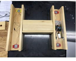
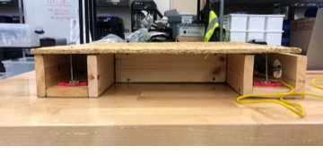
Figure 22. Different views of Fifth Prototype
Different view orientations for each
prototype can be found here.
FINAL PRODUCT
After much
work, this is our final product:
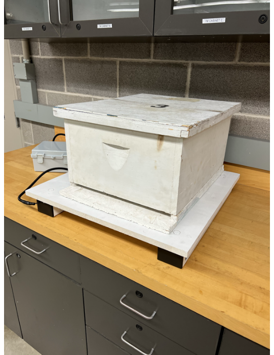
Figure 23. Final Product
The device
is made up of a series of different components that enables the user to mount their
beehives on top of it and read the weight measurements, and more importantly, fluctuations
in the weight readings.
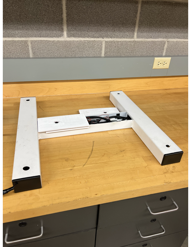
Figure 24. Rectangular Steel Tubing
holding all the electrical components
The base of
the device is a 1010 Steel Rectangular Tubing which encloses the electrical
components of the device. Such components are 6 planar beam loadcells, an
Arduino UNO board, a Bluetooth 4.0 module, and an SD card adapter. The
combination of these components allows the device to work as a whole.

Figure 25. Top wooden sheet being
placed onto the steel tubing
How it works:
Align the proper bolts coming out of the wooden sheet to the six holes on the
rectangular tubing and mount it. With proper alignment, the six bolts should
rest directly on the loadcells. With the wooden sheet mounted, the product is
ready for the beehive setup to be placed on top. When a weight is applied on
top, the bolts will hit the load cell and start generating weight readings. The
OLED display located on the side of the steel frame will display the weight
reading. Similarly, for ease of use, the user is able to monitor the weight of
their beehive setup remotely by through the ArduinoBlue App via Bluetooth.
Our project is a proof of concept
that requires further development, these are some of the pending items:
Development of proprietary app: the
team believes that even though the Arduinoblue app that is currently in use for
the final product is efficient, the development of a proprietary app would be
ideal. Such app is thought to be used for displaying the data obtained by the
loadcells and allowing the user to easily access this information remotely. The
desired mode of remote communication is Bluetooth communication since it is
objectively efficient, and it fits adequately with the specific needs of this
project.

Set-up data storage function: future
additions to the final product the team has developed include a function that
allows for the data gathered in every single reading of the loadcells to be
compiled in a single file. There are two ways in which the team believes this
could be accomplished; the development of a proprietary app or the
implementation of code that allows for the use of SD card. Ideally, within the
mobile app that would be developed to access real time data, the user would
also have the option of looking at graphs that have all the data gathered
throughout a specific amount of time. As a second option, the development of
code built into the device with the use of SD cards as a storage unit would
allow the user to retrieve such card to look at the history of the data
generated by the device.
Development of PCB Board: the team
believes that a factor that could greatly contribute to the efficiency of the
product is the development of a Printed Circuit Board. Such implementation
would allow for cost-efficiency in the project since that could replace many
components that drive the cost of fabricating the device up. In addition, the development
of the PCB board allows for more independence in the use of a proprietary app
as well as the coding language used to program the device.

IN CONCLUSION
Our Senior
Design experience was enlightening in many senses. We were exposed to a new
application of engineering in the world. In particular, we were introduced to
the involvement of engineering in disciplines of agriculture and apiculture. Further,
we had the opportunity to work in an environment that is very similar to an
actual engineering worksite. This has served as great training for us as we
prepare to start our journey into the work force. Introspectively, it made us realize
that as engineers we are bound to work in highly multidisciplinary setups where
we are required to have interactions with an array of people that come from
very different professional and technical backgrounds. As a whole, we believe
that our experience in Senior Design was tough and required a lot of hard work.
However, it provided us with a set of skills and tools that we are going to
benefit from in the professional world. Overall, the experience we have gained
these last two semesters of our Undergraduate Career was worth the long days of
hard work.
REFERENCES
Pahl,
G., and Beitz, W., 1996, Engineering design: A systematic approach, London:
Springer.
"What makes honeybees aggressive?,” last
modified 2010, accessed January 2021, https://www.honeybeesuite.com/what-makes-honey-bees-aggressive/
"Why is weighing your beehive important?,”
last modified 2021, accessed February 2021. https://www.perfectbee.com/blog/weighing-your-beehive-why-and-how#:~:text=Weighing%20your%20hive%20should%20give,how%20many%20bees)%20are%20inside.&text=Weighing%20is%20useful%20during%20other,be%20surprised%20at%20their%20speed
"The Honey Industry,” last modified 2021,
accessed February 2021. https://www.peta.org/issues/animals-used-for-food/animals-used-food-factsheets/honey-factory-farmed-bees/
"Strain Gauge Load Cell Basics,” accessed
February 2021, https://www.800loadcel.com/load-cell-and-strain-gauge-basics.html
"SolutionBee HM-6 Hive Monitor with WiFi”,
accessed February 2021, https://www.perfectbee.com/store/accessories-and-tools/monitors-and-scales/solutionbee-hm-6-hive-monitor
"Showcasing Student Innovation,” last
modified April 2018, accessed February 2021, https://forums.ni.com/t5/Showcasing-Student-Innovation/Weight-my-Bees-Measuring-Beehive-Weight-to-Monitor-Colony-Health/ta-p/3787134?profile.language=en
We went through a meticulous design process to arrive to the
final solution. The information on this page is a summary intended for the
general public. To learn about the project details, visit the DESIGN PROCESS
page. To obtain access contact the course instructor or click here.
The team
received help from various people, their help was critical to our success, we
would like to acknowledge Dr. Noe Vargas Hernandez, Dr. Joanne Rampersad-Ammons,
Mr. Greg Potter, Dr. Horacio Vasquez, and Reyes Mendoza.