UTRGV / COLLEGE OF ENGINEERING AND COMPUTER SCIENCE / MECHANICAL ENGINEERING DEPARTMENT
TEAM 7: Design of Bee Scale
(Design Process Page)

|
SDI Students (L-R) |
· Israel Falcon · Alejandro Garcia · Sabrina Dougherty · Jacob Gil
|
|
Faculty Advisor(s) |
· Dr. Joanne Rampersad-Ammons
|
|
Course Instructors |
· Dr. Noe Vargas Hernandez · Mr. Greg Potter
|
|
College of Business and Entrepreneurship Collaboration |
Dr. Sylvia Robles (Instructor) · Andy Garcia · Nicolas Perez · Matthew Woodlee · Sarah Loya |
Back to the PROJECT MAIN PAGE.
During Senior Design we followed a design process (Pahl and Beitz, 1996)., which is composed of the following steps:
Problem ID:
In this section, the objective is to identify a problem and better understand all the various aspects involved. This involves the development of Product Opportunity Gaps (POG’s) and Value Opportunity Analysis (VOA) charts.
Problem Formulation:
In this section, the objective is to further formulate the problem that was selected. This includes conducting background research on the various aspects involved with the problem, analyzing competitive products, conducting user research, identifying a value proposition and customer segment, and finally generating design specifications.
Conceptual Design:
In this section, the objective is to generate ideas that may solve the problem that was formulated. This includes developing a functional representation and resolution of the design. The creation of a morphological chart allows for the generation, design, and evaluation of concept variants.
Embodiment Design
In this section, the objective is to develop the final concept of the product in accordance with the technical and economic criteria. This step includes prototyping repeatedly as new problems, aspects, or changes arise in the design. Changes in one section will often influence another section of the design.
Testing and Validation
The objective of the Problem ID stage is to develop a full understanding of all the aspects that are involved in the problem that we are trying to solve. In this stage, we have conducted thorough research in which we assess different problems that influence different life aspects. At this stage, we acknowledged the problems caused by the dwindling numbers of bee keeping in the RGV (Rio Grande Valley) region and have looked at all the impacts this practice has on our society, environment, economy, and social justice.
POG’S
Initially, the team generated multiple POG’s in which we analyzed the problem we are trying to tackle and thought of diverse ways in which the problem could be solved. During the generation of our POG’s, we realized that the issue we were facing could be solved by the implementation of a technological product that serves as an interface between beekeepers and their beehives. The weight of a beehive can offer the beekeeper valuable insight into the state of their bees and their honey. Currently there are few products offered that are tailored to weighing beehives, therefore beekeepers go to great lengths to weigh their hive and often guesstimate. We also looked at commercially available products that attempt to solve our problem. Additionally, we looked at patents and similar products used in other fields to further develop our product. The result of the analysis we conducted was the generation of the following POG’s statement:
Our product will be of a scale that is affordable, user friendly, and easily maintainable. A smart interior design such as a corrugating structure could be implemented for less material use, exceptional weight stability, and greater cost efficiency. Rather than taking an educated guess, our product will provide a more accurate reading to the beekeeper by always resting directly underneath the beehive. The use of temperature compensated load cell will be implemented so that the weight reading will not be heavily influenced by the changes in temperature. The scale could be connected to Wi-Fi or paired through Bluetooth to provide constant readings of the weight to the beekeeper through an app or online. This is designed to maximize their knowledge of their hives and to minimize the time at which they can receive this data. To withstand outdoor conditions, the scale would be made of stainless steel or aluminum for high strength and durability on the exterior.
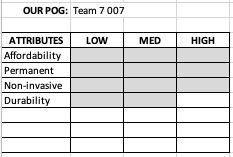
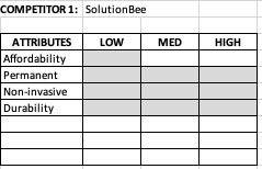
VOA
For selected POG’s, we created VOA charts that allowed us to visually analyze and compare different aspects of the devices that are already available in the market with our device. This allowed us to gain a greater understanding of some of the basic needs that our product must meet in order to be a strong competitor in the market.

FINAL PROBLEM STATEMENT
We selected a final problem; our problem statement is:
“There is a need for a device that allows people to get involved in bee keeping in an efficient way. This device should foment people to start bee keeping and continue to do so easily. The implementation of this device attempts to solve the problem of the low amount of beekeepers in the RGV region.”
The objective of the Problem Formulation stage is to generate pertinent information to the problem that has been identified in the Problem ID stage. During this stage, extensive background research was conducted to assess all the information that is related to the different aspects that are involved in the problem we are tackling.
BACKGROUND RESEARCH
To better understand the context of the problem to solve, we conducted Background Research on the following topics:
4. Bee behavior
5. Importance of beehive weight
6. Selection of materials
7. Best possible design of scale
8. Beekeeping regulations
9. Physical characteristics of beehives
10. Structural design/Corrugation
11. Load cells
An Introductory Background research video is linked here.
Our extensive Background research can be found here.
COMPETITIVE PRODUCTS
To avoid “reinventing the wheel”, we looked at existing solutions and competitive products:
Table 1: Competitive Products
|
Product |
Cost |
Description |
Available to Purchase |
|
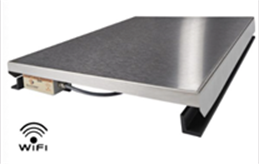
SolutionBee
|
$319.00 |
Permanent weighing device underneath beehive. |
Yes |
|
Weight My Bee
|
$1000+ |
Student project designed to weigh beehives. |
No |
|
BeeWeigh
|
$30 |
DIY mobile hive weight scale that lifts the side of the hive to determine the weight. |
No |
|
Portable Hive Scale
|
$50 |
DIY scissors-like tool to pry up one edge of hive to get half of the weight of the hive. |
No |
A detailed description of the top competitors can be found here.
USER RESEARCH
Understanding the user's wants and needs is key for the design of a valuable product, we applied a variety of User Research techniques for that purpose:
Technique #1: Stakeholder Map
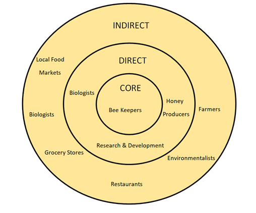
A graphical depiction of people affected by the problem is present in the Stakeholders’ Map below. At the core of the stakeholder's map is beekeepers. Because they will be directly using our product, the design will be tailored to their needs. Although they will be the main group of people using our product, other individuals and industries will be directly affected. Finally, the outer ring is composed of those that are indirectly affected by the use of our product.
Technique #2: Identifying useful information and tools.
|
What user information could be useful? |
What user research tool could you use? |
|
Is there something you do not like about the product? |
Customer Surveys, Focus Groups, Customer Complaints |
|
What problems arise from beekeeping? |
Customer Interviews, Ethnography |
|
Other methods for weighing beehives |
Human Factors, Task analysis |
|
Available Products |
Dissection, Warranty Data, Customer Surveys |
Technique #3: Interview questions
· Do you weigh your beehive?
1. If so, how?
1. If not, how do you determine when to harvest the honey?
3. How much do your hives weigh on average?
5. What do you think would improve efficiency?
· What other information do you want to know about your beehive, that is not easily obtainable?
6. How do you monitor your bee population?
a. How much honey is produced per hive?
Listed above are some interview questions tailored to local beekeepers. Their responses to these questions should give ample information that should help in the design of our product.
Interview with Dr. Rampersad-Ammons (Researcher)
2. Describe the research that is being conducted?
1. Researching the bee’s behavior and specifically Africanized bees.
3. Do you currently weigh your beehives?
1. No, I currently don’t weigh my hives.
4. How much do they weigh approximately?
1. About 250 to 300 lbs.
5. How do you monitor your bee population?
1. By going into the hive and looking at it manually without any automation technology, using traditional methods. Smoking them to help adjust the hive for maintenance. Uses a type of safety suit looking like a “Michelin man” to stop bee stings.
6. How to start beekeeping?
1. Generally started off with a pound or two of bees, shipped via mail.
7. How to expand the hive?
1. By stacking another bee box hive on top of the other for expansion.
8. Additional Suggestions
1. No wood is used for exterior purposes due to moisture deteriorating the material and can affect the bee’s home.
Technique #4: Customer Experiences
SolutionBee User Experience:
The user of this product explains in great depth the typical weight change interpretations he perceived such as:
· Nectar flow
· Post nectar flow
· Post honey harvest
· Swarming
· Feeding time
· Weather impacts
· Hive inspections
· Beehive robbery
The users' extensive experience is expanded here.
By analyzing this customer experience, some conclusions can be made. Keeping track of the weight of a beehive can help a beekeeper maintain a colony for a longer time, thus allowing the production of honey to increase significantly. Moreover, weighing and learning about what each graph can represent will assist new beekeepers to maintain a hive. Finally, this reveals what our competitors offer and what their customers experience. This further influences some aspects of the design of our product.
Need for Weighing Bee Product
The writer from the website clearly states out the problem he/she experienced as a first-year beekeeper.
1) I had 2 out 3 hives swarm. I think.
2) I experienced a Tulip Poplar nectar flow. I think.
3) I saw bees gather nectar – some days more than other days. I think.
The writer places emphasis on the I think because there was no way for her to have evidence to understand the changes of the beehive.
The writer claims if they had a device to weigh bees, they would have known:
1) I would know the population of the runaway swarm …estimated at 3500 bees per pound.
2) I would know the mass of nectar (and pollen) gathered during the day and of water evaporated at night
3) I would know the number of bees foraging by monitoring the loss of weight in bees leaving in the morning.
4) I would know the rate of growth of daily nectar collection as a nectar flow began.
5) I could compare my hives with the hives of others and with my own hives in previous years.
The claims made above from the perspective of a first-year beekeeper emphasizes the need/want for our product. The lack of this product appears to have withheld information about the state of the beehive. Having access to this information could help a beginner beekeeper understand the needs of their beehive and grow to become more successful.
DESIGN SPEC
The Design Specification captures the “essence” of the design, the following table shows the Design Spec for our project:
D: Demand
W: Want
|
Design Requirements |
D/W |
|
|
Lightweight: < 15lb |
W |
Easy to remove, clean, & setup |
|
Durable: withstand outdoor conditions & constant weight |
D |
Last longer, maintains correct value of weight, parts don’t have to be replaced. |
|
Real Time Data: display output readings constantly |
D |
Allows easy maintenance of the bees, determine any issues discovered. |
|
2.4 GHz Wi-fi radio: access data remotely about 150 feet |
W |
Provides a powerful signal and quick real time data |
|
Remain directly underneath hive |
D |
Will not disturb the bees, consistently collect the weight |
|
Appealing design |
W |
Does not disrupt the looks of the beehive, catches bee's attention |
|
Low-cost: < $150 |
D |
Affordable, easy to start for new beekeepers |
|
NFC: access data instantaneously using application |
W |
Most reliable way of gathering weight measurement, another quick alternative |
|
Bluetooth: access data remotely about 300 ft |
W |
Does not have to be near hive to collect data, safer for beekeepers incase bees are aggressive |
|
Battery: Nickel-cadmium |
W |
Very cheap, rugged, large capacity |
|
Battery: Lithium |
W |
Cost effective, widely available, long lasting |
|
Battery placement: easily accessible/replaceable |
D |
Allows easy replacement, user friendly for changing battery |
|
Dimensions of platform: 20” x 18” |
D |
Allows the beehive to fit on top |
|
Regulation: noninvasive |
D |
Will not affect the bees, allow continuation of honey production |
|
Framework Design: corrugating structure |
W |
Provides durability and strength to last longer |
|
Framework material: Polymer/Aluminum/Stainless Steel/Wood |
D |
Any of the materials will assist in longevity |
|
Platform material: Aluminum/Stainless Steel/Wood |
D |
Any of the materials will assist in longevity |
|
Load Cell: Temperature compensated/actively compensated |
D |
Avoid inaccurate readings based on readings of temperature |
|
Load Cell Capacity: 400lbs |
D |
Beehives usually reach 400 lbs, provides a safety net incase weight increases greatly |
|
Output reading: weight measurement |
D |
Helps perceive what is occurring with the beehive |
|
Unit output: English system |
W |
Easier to read in US |
|
Collection and Transmission of data: webpage/app |
D |
Easy access and storage to actively keep track of the information displayed by scale |
|
Color: non bright |
W |
Bright colors could attract unwanted bees |
|
Coating: epoxy paint |
W |
Provides longevity and protection from outside conditions |
|
Feet design: flat feet under the load cell |
D |
Easiest way to collect weight, stops from constant cleaning |
The objective of the Conceptual Design stage is to initialize the process of physically developing our product. The earlier stage of the process involves the theory behind the product, as well as the problem that is being tackled and its implications. During the conceptual design stage, we have stated developing ideas to select the proper physical components of the device in order to start the construction of the device. The conceptual design also involves the development of different charts that assist in the process of selecting the right materials and configuration to assemble the device together.
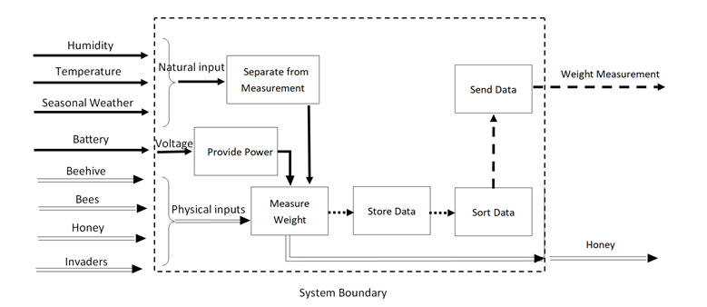
FUNCTIONAL DESIGN
Creating a Functional Reasoning allows us to understand what the product needs to do, and not necessarily how.
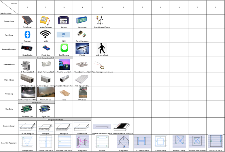
MORPHOLOGICAL CHART
The Morphological Chart helps us explore the universe of possible solutions for each function in an orderly fashion.
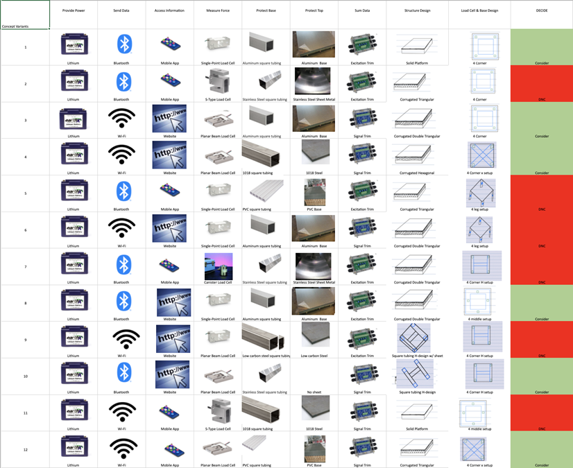
CONCEPT VARIANTS AND SELECTION PROCESS
Combining all possible solutions would generate a factorial number of concept variants, we had to be selective to find the best ones.
12 Concept Variants:
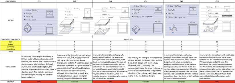
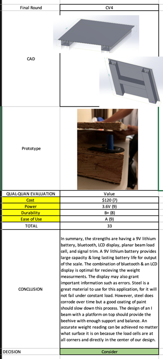
First Round:
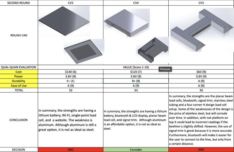
Second Round:
FINAL CONCEPT(S)
After the selection process we arrived at the Final Concept.
The objective of the Embodiment Design stage is to incorporate all the knowledge acquired regarding the project in previous stages of the design process to initialize the physical actualization of the project. During this process, we have started prototyping repeatedly in order to gain a fuller understanding of the physical aspects that surround our project. This design is subsequent to the conceptual design in which we selected our final concept and have been working towards the final physical actualization of such final concept.
STRATEGIES AND PRIORITIES
Entering the embodiment design stage, a final concept had been previously selected. Although we had a basic understanding of the components we had selected for our (or that would build our) design, the team did not have complete confidence in how the final product was going to be achieved. In order to reach a high level of confidence, we knew prototyping would help recognize possible faults in our concept. Also, constantly discussing and questioning how all the components worked with each design allowed us to visualize the success of the outcome. The list below shows our developed list of questions that arose from working on the prototypes. With this, we believe we will be able to incorporate the design specifications we have previously stated to be featured in our device.
1. How will the load cell be secured in place?
2. How will the load cell deflect in order to obtain a reading?
3. How will the platform react to the load?
4. How will we protect the electrical components from external inputs (moisture, insects, etc.)?
5. What dimensions does our design require the rectangular tubing to be?
6. Once assembled, what calibration techniques will be employed?
7. How can we implement 5+ load cells in our circuit?
8. How can we simulate the behavior of the components and system with the beehive?
9. How can we get valuable data from the loadcells on a display?
10. How can the user access the information generated by the device?
11. How can we implement our display into our product?
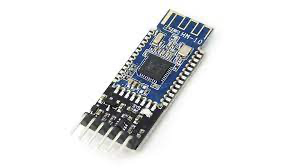
12. How can we communicate data over Bluetooth?
TASK 1: SECURING LOAD CELL
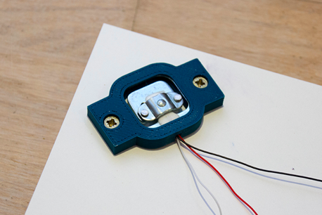
To ensure the security of the load cell within the system we implemented a 3D printed encasing. This encasing is to keep the load cell in one place in the event of the product being violently moved around. The encasing must have specific mechanical properties such as certain rigidity in order for them not to break as force in compression is put on them. The desired mechanical properties that the encasing must have are dependent on the material used to print them. To obtain the best properties pertinent to the performance of our encasings, the team selected 3D printing with PETG to ensure the encasing can withstand high compression loads.
TASK 2: LOAD CELL DEFLECTION
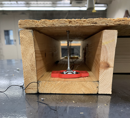
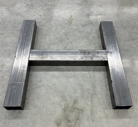
In order for a load cell to obtain a weight measurement reading, the center of the load cell must deflect. The strain gauge, which is located on the center of the load cell, measures the displacement of the center as it is pushed down while the outside section of the load cell remains on a flat center. The team recognized how an encasing was needed to secure and raise the load cell above a solid ground. The team consider resting the load cell on top of the rectangular beam with a hole underneath to allow for the deflection to occur. Another consideration was placing the load in the middle of the rectangular tubing being held in place by a 3D printed structure. By attaching these ideas to our prototypes, often the desired placement resulted in the addition of difficulties in our design. The idea that the team has chosen to move forward with a 3D printed case for the loadcell. This case will raise the load cell off while the ground while being screwed onto the rectangular tubing.
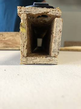
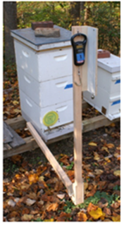
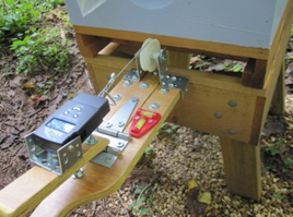
The images above show the placement of the load cell on top of the tubing with a hole underneath to allow for the load cell to deflect.
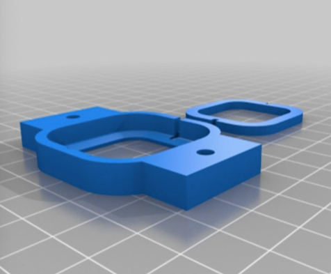
The image above shows the encasing of the load cell the team will implement.
The image depicts the selected placing of the loadcells along with the appropriate configuration of the base extensions.
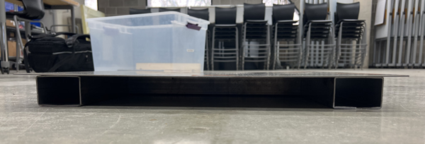
TASK 3: PLATFORM DEFLECTION
As observed from the early stages of prototyping, the platform on top of the base of our device will be under constant compression due to the load of the beehive which sits on top of it. Because of this, the platform will present bending which is a natural phenomenon occurring in setups such as the one in our device. Given that some of the earliest prototypes have been made from compressed wood, the deflection observed in the platforms of these has been a magnified version of the actual deflection which the steel sheet platform will present. Nonetheless, the objective of this task is to determine the deflection that will arise as a consequence of the structural design as well as the constant load that will be caused by the position of the beehive. For the calculations of the deflection of the platform, such platform has been modeled as a simply supported beam with a concentrated center load acting on top of it.
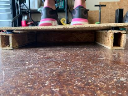
Picture of Early Prototype with Significant Deflection
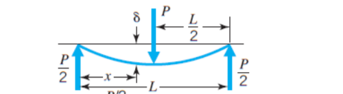
Diagram of Deflection Across a Simply Supported Beam with Concentrated Center Load
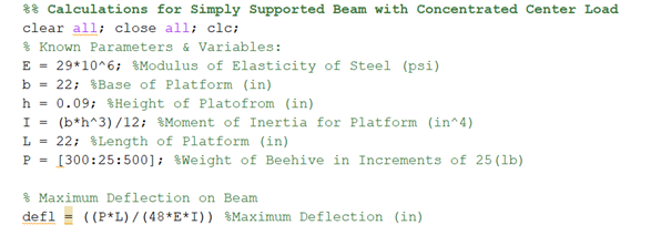

The results obtained from the calculations above were obtained by modeling the platform as a simply supported beam with a concentrated center load. Even though the setup does not match the modeling completely, this modeling still provides with a good estimate to calculate the maximum deflection that would be present on the platform. The results are an array of deflections since the way in which these results were calculated was by setting a minimum value for the weight of the beehive (300 lb.) and increasing this value with increments of 25 lb. Therefore, the deflections obtained in this simulation account for the potential weight of the beehive at different stages that conclude at the final stage of the beehive in which its maximum weight could round somewhere between 450-500 lb.
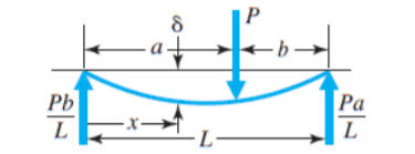
Diagram of Deflection Across a Simply Supported Beam with Concentrated Load at any Point
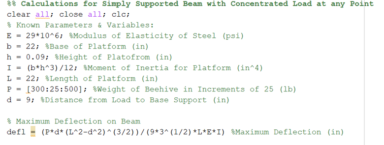

The results obtained from the second iteration of calculations are similar to the ones obtained in the previous simulation with a punctual difference: the location of the concentrated load is on longer at the center. For this second simulation, the location of the concentrated load was placed at 9 in from the support provided by the rectangular tubing base. This was done to account for any irregular mounting of the beehive on top of the platform which, as seen from the results, yields significant changes in the deflection of the platform. This second iteration also features the different potential weights of the beehive at one single position located at 9 in from the support.
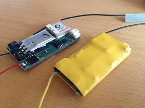
TASK 4: PROTECT ELECTRICAL COMPONENTS
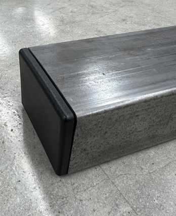
To protect the electrical components, shrink wrap will be used to keep any kind of moisture out of the circuitry. Additionally, shrink wrap helps keep the soldering connections in place in case the product is bumped around violently, and a rubber boot will be used to surround the load cell and protect it from the outside environment. At the end of the steel tubing, there are large openings which offer easy access for maintenance. However, this also offers easy access for water and insects to enter. Therefore, a plastic end cap will be used to close off the openings, which will seal out the external factors.
TASK 5: RECTANGULAR TUBING DIMENSIONS
The team had recognized rectangular tubing was going to be use; however, the dimensions of the tubing weren’t finalized. Although the team had to consider how the rectangular tubing would support the top platform with the heavy load, the team had to consider the electrical components would fit properly. In order to decide on final dimensions, the team simply had to ensure the larger component would fit.
Angled view with plastic end caps attached to the tubing
TASK 6: CALIBRATION TECHNIQUES
Before this project, the team had no experience with load cells. Although the team has been gaining a greater understanding of how the load cells work, the embodiment stage allowed this understanding to grow. Although 50kg load cells were used and ordered, the team recognized the possibility of inaccurate devices. Therefore, the team understands calibrate the load cells to ensure they are measuring correctly and accurately. Before implementing in design, the load cell should be calibrated to ensure accuracy is reached. Also, when the load cell is placed within the design, an eccentricity test should be taken to test how much the effect of location has on the load. Repeatability tests have been conducted on a working prototype to calibrate the loadcells in the device. The technique used to obtain the calibration consists of comparing the values obtained from measuring the mass of different objects with our device and then comparing those measured values with the actual values of the mass of those objects. The data was then plotted onto a graph and the equation of the line obtained was used to calibrate the loadcells to obtain an accurate mass reading. This test was conducted several times and with different objects to test consistency and accuracy.
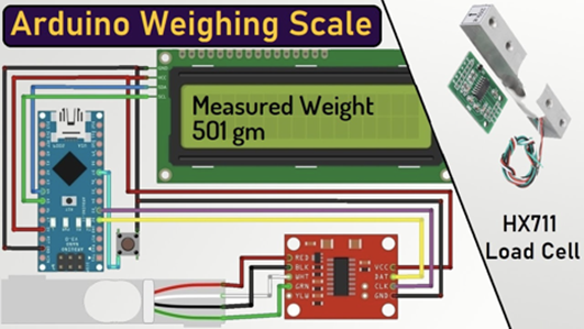
The team found a calibration code that would ensure the accuracy of the loadcells. This also helped with gaining a general knowledge of how Arduino code communicates with the loadcells and the HX711 amplifier. This is one of a series of Arduino codes the team used to eventually find a final code that would be used for our project.
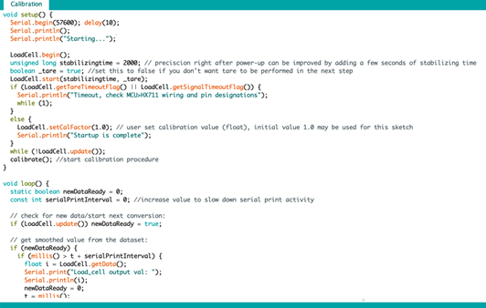
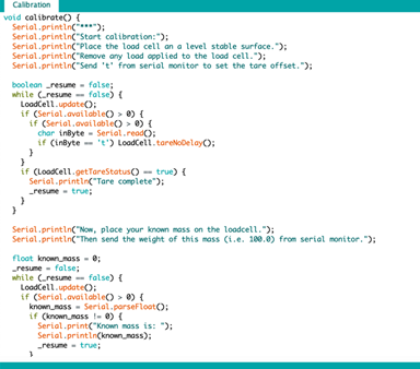
We ran a series of tests with the following Arduino Code to develop a Calibration curve.
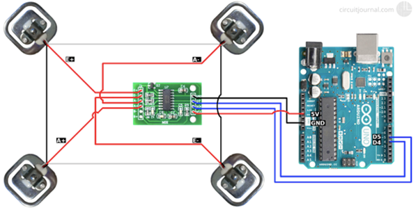
TASK 7: 5+ LOAD CELLS
The team had originally decided to implement four 50kg load cells on the structure. With four 50kg load cells, the scale was going to be able to read approximately 440 pounds, which is higher than the median weight of beehives. However, following prototyping and noticing the deflection of platform with load, the team recognized the need for additional load cell(s). Most standard weight scales have four load cells. However, the team plans to do further research to understand how to add additional load cells.
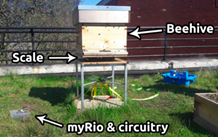
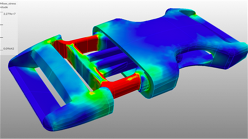
TASK 8: SIMULATING RESPONSE OF COMPONENTS
To gain a greater understanding of how the load will act on the structure, the team plans to do a FE analysis on the structure. This will allow the team to analyze how the structure will react under varying loads and different beehive placement. This will help the team reduce the number of physical prototypes and experiments, and it will allow the team to better develop their design.
TASK 9: DEVELOPMENT OF ARDUINO CODE
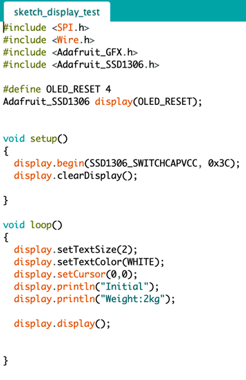
The Arduino code below is to strictly test the OLED display. This code allowed us to understand the basic Arduino controls that are needed to communicate the Arduino board to the display.
BASIC DISPLAY CODE
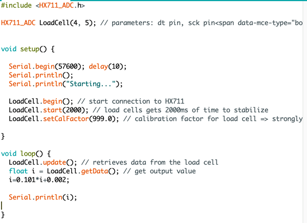
The following includes the code to obtain a weight reading using the Serial Monitor.
LOAD CELL READING
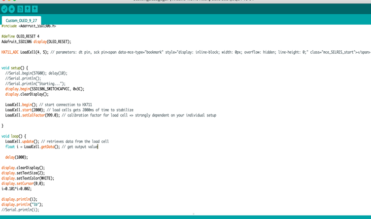
The following shows the combination of the display and loadcell code. The Serial Monitor was commented out because it will not be useful towards the final design.
DISPLAY & LOADCELL
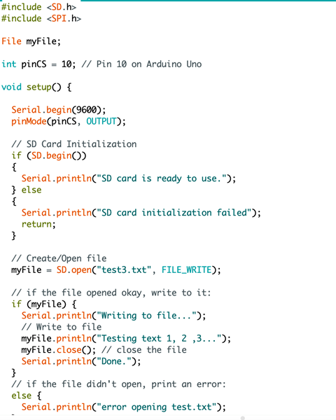
Below is the Arduino code for a micro-SD card that will create a file to store the weight readings. The data in the file allows the user to either receive the values over Bluetooth or by removing the SD card.
SD CARD
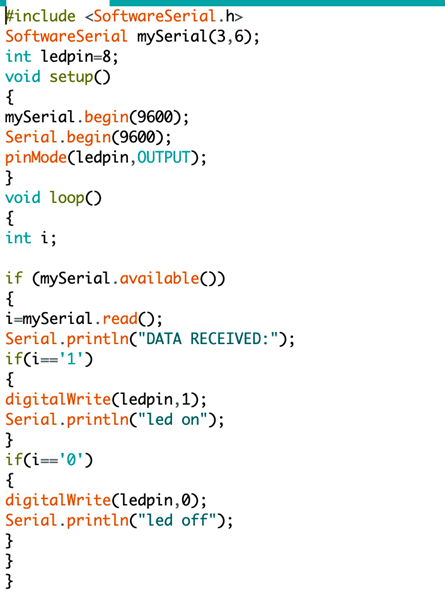
This code below allows for the Bluetooth module to power on and off an LED light. This helped us ensure the Bluetooth module and Arduino were able to function wirelessly.
BLUETOOTH
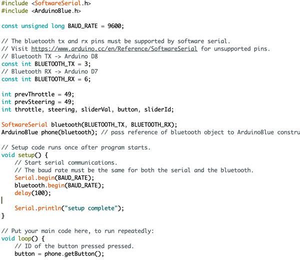
Below is an Arduino code for the Arduinoblue app, which can be found on iOS and android app stores.
ARDUINOBLUE
TASK 10: DEVELOPMENT OF WEB/IOS APP
With this code, the Bluetooth module was able to connect to a phone. No commands or UI

This code communicates the app with the Arduino serial monitor.

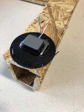
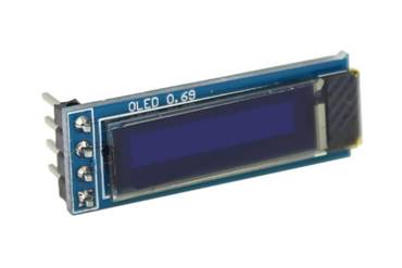
TASK 11: IMPLEMENTATION OF OLED DISPLAY
Although the user will be able to access information remotely through a Bluetooth connection, an OLED display will also be attached to the side of the scale. The display allows the user to have access to the current weight reading of the beehive. This is simply an alternative option presented to users in order to access data from their beehive. The team had to develop an Arduino code that would allow for the display to communicate with the HX711 amplifier. This code, which was previewed above, would gather the data obtained from the loadcells and convert it into text that can be displayed on the OLED display.
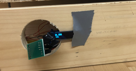
Rough representation of working display on prototype
TASK 12: BLUETOOTH COMMUNICATION
The preferred communication method for the user to obtain data from the device is by communicating with it via Bluetooth. The product features a Bluetooth module that is connected to the Arduino board and can communicate to the user’s phone to send and receive information. The team has had to develop several iterations of Arduino codes to get a better understanding of the way Bluetooth modules communicate with the Arduino. Additionally, after communication with the board has been granted, communication with the user’s phone is required. Setting up the connection with the Arduino board involves coding that sends the weight readings from the HX711 amplifier to the Bluetooth module. As well, the team is working on developing another code to develop an app that would enable the user to access the information from the Bluetooth module.
ANALYSES (FMEA, QFD, and Business Model)
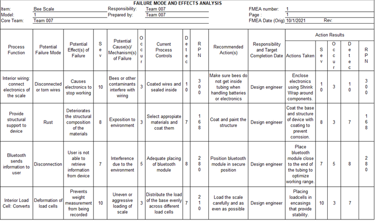
FMEA conducted on the device
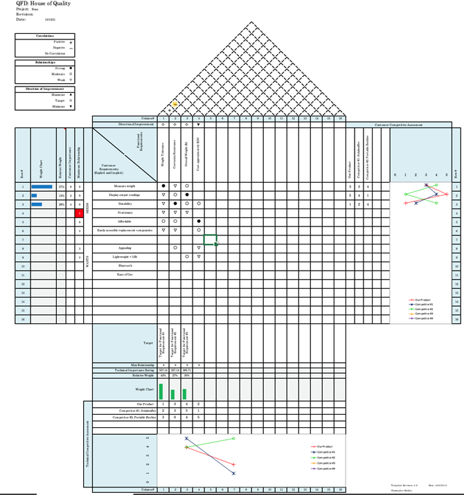
QFD House of Quality
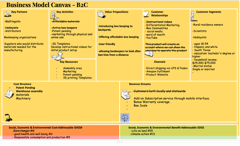 Business
Model Canvas
Business
Model Canvas
The objective of the Testing and Validation stage is to ensure that the product under development yields results as accurately as possible and consistently. During this stage, several iterations of the actions the product will have to perform during its operational life are conducted to obtain quantitative information on the performance of the components that make up the device. This stage is vital to the development of products since it allows the designers to verify the integrity and the quality of the product they are developing.
TEST 1: BLUETOOTH MODULE WORKING RANGE
This is the testing protocol that enabled us to determine the working range of the Bluetooth module that will be used in our product. This test was conducted in two different ways to accurately recreate the potential scenarios our product will be under when in use. The working range of the module was tested in both inside and outside conditions since a combination of both scenarios might be present in the field where the product will be. The quantitative data obtained from this protocol allowed us to determine that the working range of our Bluetooth module is made up of two different components: working range after being connected from a relatively short distance and maximum distance at which users can connect to the Bluetooth module. The testing showed that the maximum distance at which the module can remain connected is about 396 ft (120 m) and the maximum distance at which a user can connect to the module is about 260 ft (80 m). This data is consistent with the manufacturer’s data relative to the Bluetooth module.
TEST 2: LOAD CELLS CALIBRATION
In this testing protocol, we developed a strategy that allowed us to calibrate the loadcells in our product to read accurate mass measurements. The test entailed the use of mass measurements of different objects which were obtained by using a conventional weight scale and then comparing them to the ones obtained with our device. Our device returned values which were read by the loadcells, which did not correspond directly to any unit system. After repeating several iterations of the mass measurements, we were able to realize there was consistency in our readings and a clear pattern. We compared the readings we were getting with the known masses of the objects we measured. A curve of the actual mass compared to the mass read by our device was generated and the equation of the line allowed us to determine the calibration required for the readings obtained in our device to be consistent with a system of units. The accuracy of our device in comparison to a conventional commercially available weight scale is around 2%.
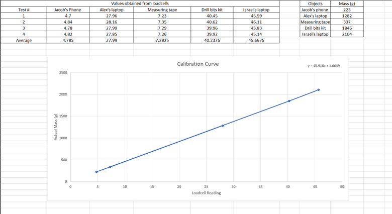
|
Object |
Calibrated Value |
Actual Value |
Error |
|
Jacob's phone |
221.37296 |
223 |
0.729614 |
|
Alex's laptop |
1286.85374 |
1282 |
0.378607 |
|
Measuring tape |
336.04817 |
337 |
0.282442 |
|
Drill bits kit |
1849.20995 |
1846 |
0.173887 |
|
Israel's laptop |
2098.53383 |
2104 |
0.259799 |
|
avg |
- |
- |
0.36487 |
TEST 3: DESIGN INTEGRITY
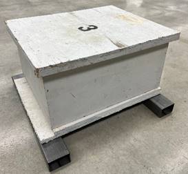
The integrity of the design selected was tested by placing different loads on top of it to replicate the actual loads that will be used in the operational time of the product. The design and materials selected were tested repeatedly to select a combination of both parameters that would optimize the results obtained. The selected design proved to withstand high loads without breaking or compromising its integrity. Additionally, the materials used in the final product were tested for bending, deformation, and rigidity. The results suggested that the materials will be able to withstand the loads that will be put on them when in operational use. In addition, testing with an actual beehive allowed the team to confirm that the configuration of design and dimensions selected will allow the device to hold the beehives adequately.
Pahl, G., and Beitz, W., 1996, Engineering design: A systematic approach, London: Springer[nv1] .
"What makes honeybees aggressive?,” last modified 2010, accessed January 2021, https://www.honeybeesuite.com/what-makes-honey-bees-aggressive/
"Why is weighing your beehive important?,” last modified 2021, accessed February 2021. https://www.perfectbee.com/blog/weighing-your-beehive-why-and-how#:~:text=Weighing%20your%20hive%20should%20give,how%20many%20bees)%20are%20inside.&text=Weighing%20is%20useful%20during%20other,be%20surprised%20at%20their%20speed
"The Honey Industry,” last modified 2021, accessed February 2021. https://www.peta.org/issues/animals-used-for-food/animals-used-food-factsheets/honey-factory-farmed-bees/
"Strain Gauge Load Cell Basics,” accessed February 2021, https://www.800loadcel.com/load-cell-and-strain-gauge-basics.html
"SolutionBee HM-6 Hive Monitor with WiFi”, accessed February 2021, https://www.perfectbee.com/store/accessories-and-tools/monitors-and-scales/solutionbee-hm-6-hive-monitor
"Showcasing Student Innovation,” last modified April 2018, accessed February 2021, https://forums.ni.com/t5/Showcasing-Student-Innovation/Weight-my-Bees-Measuring-Beehive-Weight-to-Monitor-Colony-Health/ta-p/3787134?profile.language=en
"Weighing scale calibration – How to calibrate weighing instruments,” last modified May 16, 2017, accessed May 2021, https://blog.beamex.com/weighing-scale-calibration-how-to-calibrate-weighing-instruments#Preparations-before-calibration
This is a summary of important Senior Design files, click on each to open in a different window[nv2] .
SDI
REVIEWS
R2
RN
MIDTERM
PRESENTATION
FINAL
PRESENTATION
REPORT
SDII
REVIEWS
R1
R2
RN
MIDTERM
PRESENTATION
FINAL
THIS WEBSITE