UTRGV / COLLEGE OF ENGINEERING AND COMPUTER
SCIENCE / MECHANICAL ENGINEERING DEPARTMENT
TEAM 3: Mesquite
Bean Harvester

|
Students
(L-R) |
· Carlos
Guzman · Victoria
Garza · Stephanie
Ramos · Alexandra
Salinas |
|
Faculty Advisor(s) |
· Dr.
Arturo Fuentes · Dr.
Joanne Rampersad-Ammons · Mr.
John Pemelton |
INDEX
For
our Senior Design process, we made an effort to address and consider every
detail to determine our final concept and product design. Our design process
consists of five sub-processes, which are used to guide us to a final product.
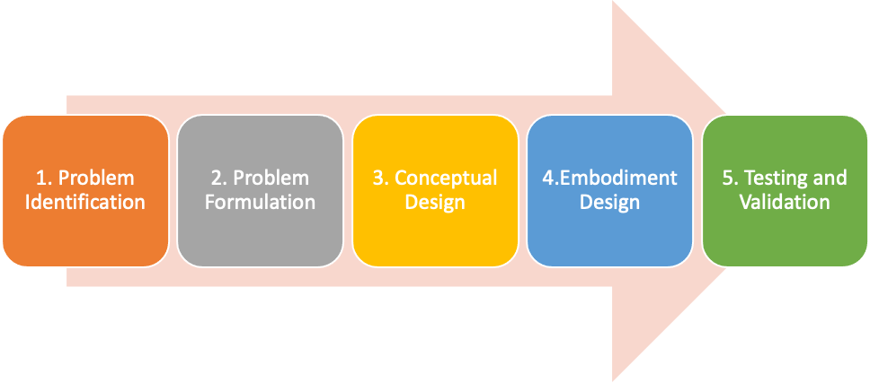
Figure 1:
Design Process
·
1. Problem Identification
Clearly
identifying a problem is imperative for the design process because it is the root
of the project. Determining the central issue of a certain subject can allow
one to focus on that problem without deviating from it and allow one to develop
a problem statement. [4]

· 2. Problem Formulation
Clearly
defining the problem is essential to the design process. This consists of finding
and learning about the major and minor details of the problem subject to make
well-educated decisions regarding the central issue. The methods of problem
formulation include background research, research on competitive products, user
research, and design specifications. [3]

· 3. Conceptual Design
A
crucial aspect of the design process is to determine the functions of the
product that are sought to solve the problem that is identified. Within these
functions, solutions can be presented specifically to those functions and cohesively
brought together into concept variants. From here, a final design can be
determined based on qualitative or quantitative eliminations.
· 4. Embodiment Design
The
embodiment process brings the final concept to life and requires using engineering
aspects to tackle technical questions. The design specifications of the product
itself are considered, and the final design is realized.

· 5. Testing and Validation
In
this final sub-process, the final design is tested, evaluated, and optimized so
that it can be used to effectively solve the problem identified. After testing
and validation, the final product can be directly led to a higher level of production.

Clearly
identifying a problem is crucial for the design process because it is the root
of the project. We, as a team, have decided to make an impact within our local
community by tackling a problem introduced by mesquite farmers within Linn,
Texas.
Product Opportunity
Gap
Given
the growing trend for healthier foods and products, there is a greater demand
for mesquite beans. Because the main harvesting method of the mesquite industry
is manual labor, which is very strenuous and time-consuming with minor
results, there is a demand for a new and more efficient way for harvesting
mesquite beans.
Value Opportunity
Chart (VOA)
For
our Product Opportunity Gap, we developed a Value Opportunity Chart (VOA),
which directly compares Manual Labor to our prospective product. The purpose of
these two graphs is to compare the ideal solution to that of the current
workflow of the Cappadona Ranch.
Table 1: Value Opportunity Chart
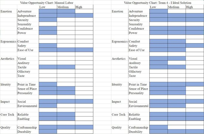
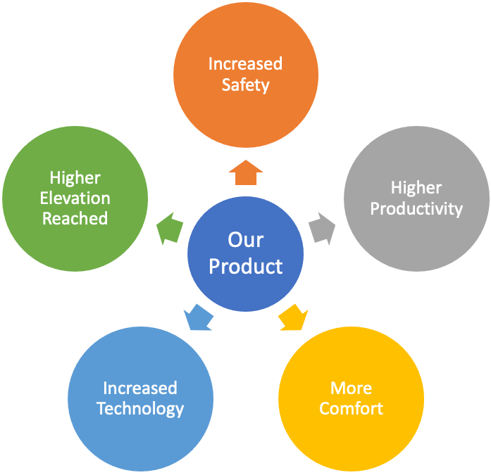
Figure 2:
Describing Our Value Opportunity Chart
Although
our product would have these clear advantages over manual labor, our product
would have a couple of drawbacks.
-
The first
drawback of our product would be that it would need proper training for
operation. However, this is specific towards the safety of the user.
-
The
second drawback would be that our product may not be as effective as manual
labor in their ability to access to hard-to-reach areas.
-
Despite
the drawbacks of the product, with safety being an upmost priority, the pros
certainly outweigh the cons of manual labor, especially considering the safety hazards
that the current field workers must go through every year during harvest
season.
FINAL PROBLEM STATEMENT

Click the icon above to hear our
Final Problem Statement!
Clearly defining the problem is
essential to the design process. The methods of problem formulation include
background research, research on competitive products, user research, and design
specifications.
BACKGROUND
RESEARCH
To better
understand the context of the problem to solve, we conducted Background
Research on the following topics:
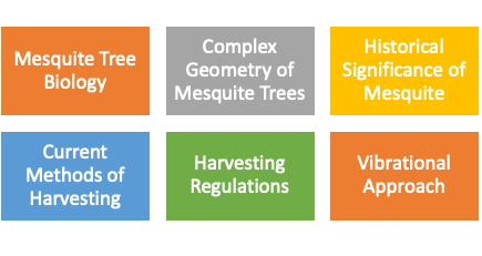
All the sub-categories above are
incredibly important when setting up the foundational work of the design
process. With all of these in mind, we can use the knowledge gained towards
conceptual design work.
To view our Background Research folder,
view here.
COMPETITIVE
PRODUCTS
To avoid
“reinventing the wheel,” we looked at existing solutions and competitive
products:
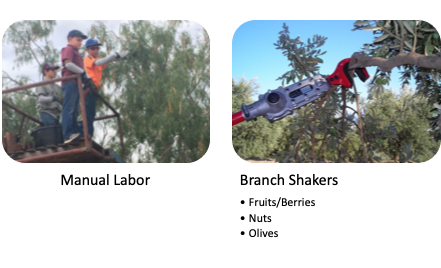
Much of the references that were
looked at for competitive products were that in use for agriculture. For
example, the hook as shown above is a Kadıoğlu Emr400 Branch Shaker Harvesting Machine. This
mechanical hook is used for vibrational applications to branches and is one of
the many competing products that were found during our research.
To view our Competitive Products
folder, view here.
USER RESEARCH
Understanding
the user wants and needs is key for the design of a valuable product, we applied
a variety of User Research techniques for that purpose:
Technique #1: Stakeholder Map
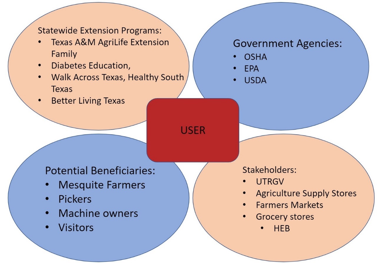
Figure 3:
Stakeholder Map
Our
stakeholder map shows us the people and businesses that will be directly
affected by the decisions made for our designs. To assist with understanding
the user and the pains and gains of the business, we have conducted a personal
interview between the team and the Cappadona family, which can be heard below.
Technique #2: Scenario Development

Click on the icon above to view our
Scenario Development!
To view our Scenario Development
document, view here.
Technique #3: Interview with the Cappadona’s

Click the icon above to hear the audio file
from our interview with the Cappadonas!
To view our notes from our Interview
with the Cappadonas, view here.
DESIGN SPECIFICATION
The Design
Specification captures the “essence” of the design by showcasing the demands
and wants of our users. The following table shows the Design Specifications for
our project:
Table 2: Design Specification Table
|
Date
Changed |
Demand/Want |
Requirement
List for the Mesquite Bean Picker |
Responsibility |
|
2/18/2020 2/18/2020 5/1/2020 3/3/2020 3/3/2020 |
W D D D D |
Geometry Maximum Radius
-- 24 ft. Average Canopy
Radius – 15 ft. Telescoping Arm Extender - 6
ft - 12 ft. Localized
Collection (1/4th of Canopy Area) Vibration
Interface – Meets Branch Perimeter |
|
|
3/3/2020 3/3/2020 3/3/2020 3/3/2020 3/3/2020 3/3/2020 |
D W W W D W |
Energy Localized Vibration Battery –
24 Volt Battery (Car Battery) Gasoline/Motor Rotational Gravitational
Freefall Electric (for
Vibration) |
|
|
3/3/2020 3/3/2020 3/3/2020 3/3/2020 3/3/2020 |
D D D W W |
Material Heavy Duty Material for
Tarpaulin Aluminum Arm Extender Steel Branch
Interface Aluminum Frame
(Tarpaulin) Aluminum Hopper |
|
|
3/3/2020 3/3/2020 |
D D W W |
Signals Dial for
Vibration Control LED Light LED
Display Sound for
I/O of Vibration Interface |
|
|
3/3/2020 3/3/2020 |
W D D |
Safety No sharp
blades Remove the user
from physically touching the tree due to thorns Remove the need
for standing on elevated height |
|
|
3/3/2020 3/3/2020 3/3/2020 3/3/2020 3/3/2020 3/3/2020 |
D W W D W W |
Ergonomics Low profile to
account for small canopy height <
50-75 lb. to
Maneuver the collection device Can be easily
pushed by physical effort <
125 lb. for Easy Movement Ease of Use Handheld
Vibration Machine |
|
|
|
W |
Costs < $400 for
the whole project |
|
To view more details about our Design
Specifications, view here.
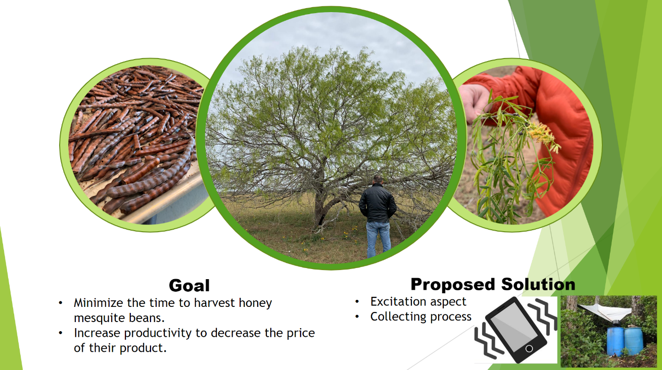
Figure 4:
Our Goal and Proposed Solution on a single PowerPoint slide
A crucial aspect of the design process is to determine the
functions of the product that are sought to solve the problem that is
identified. Within these functions, solutions can be presented specifically to
those functions and cohesively brought together into concept variants. From
here, a final design can be determined based on qualitative or quantitative
eliminations.
FUNCTIONAL DESIGN
Creating a
Functional Diagram allows us to understand what the product needs to do but not
necessarily how.

Figure 5: Functional Diagram
Although our Functional Diagram shows
only one function, we decided to divide our project into two parts. One
function for Picking Mesquite Beans and the other for Collecting Mesquite
Beans. Each of these functions contain sub-functions within themselves.
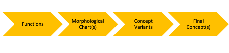
MORPHOLOGICAL
CHARTS AND SUB-FUNCTION CHARTS
The
Morphological Chart helps us explore the universe of viable solutions for each
function’s sub-function in an orderly fashion. The Sub-Function Chart helps us
to decide on the best solution for the specific sub-function based on certain criteria.
Function #1: EXCITATION
Table 3: Excitation Morphological Chart
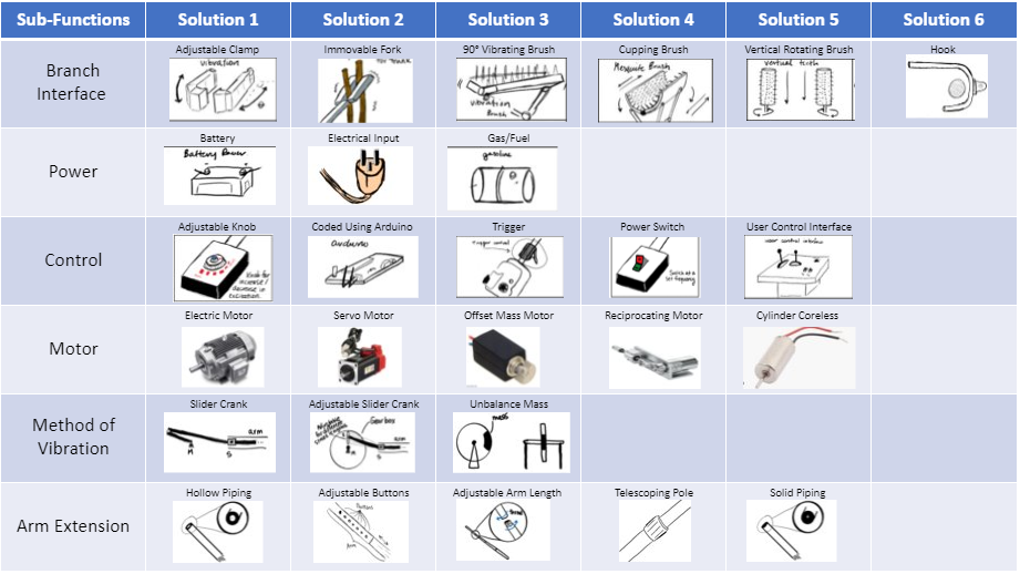
The Excitation function is broken down
into six functions: Branch Interface, Power, Control, Motor, Method of
Vibration, and Arm Extension.
Table 4: Excitation Subfunction Chart - Branch Interface
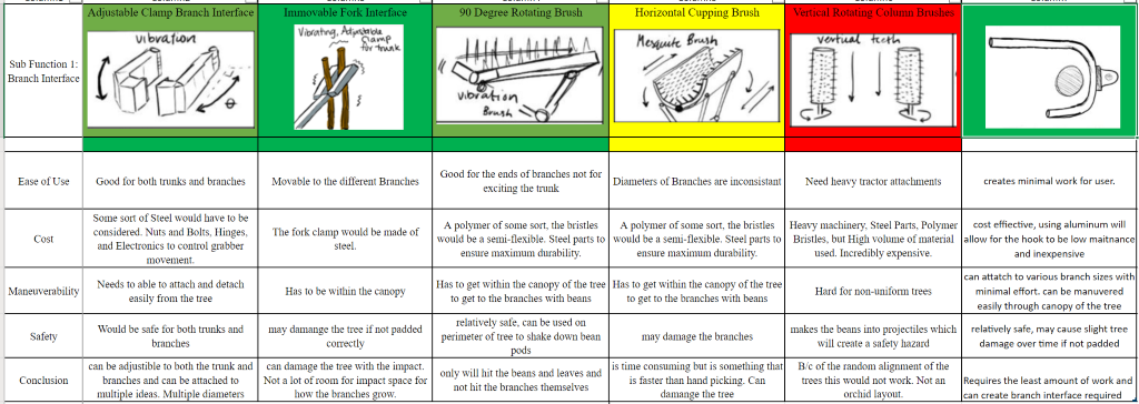
The Branch Interface requires connection between
the machine and the branch to allow for constant vibration. This
subfunction is comparing all its solutions to the following criteria: Ease of
Use, Cost, Mobility, and Safety.
Table 5: Excitation Subfunction Chart - Power Supply
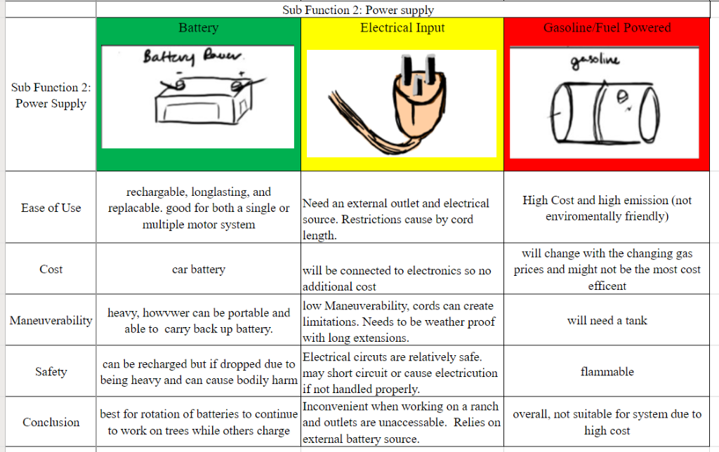
The second subfunction is the Power
Supply. Its solutions will be compared using the following criteria: Ease of
Use, Cost, Maneuverability, and Safety.
Table 6: Excitation Subfunction Chart - Control
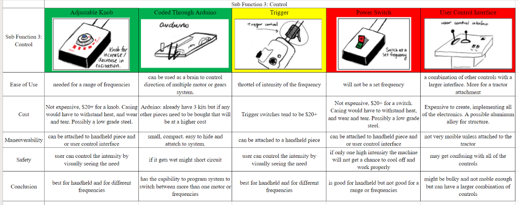
Control is essential for both holding
the vibration frequency and for connecting the machine together. Its solutions
will be compared using the following criteria: Ease of Use, Cost,
Maneuverability, and Safety.
Table 7: Excitation Subfunction Chart - Motor
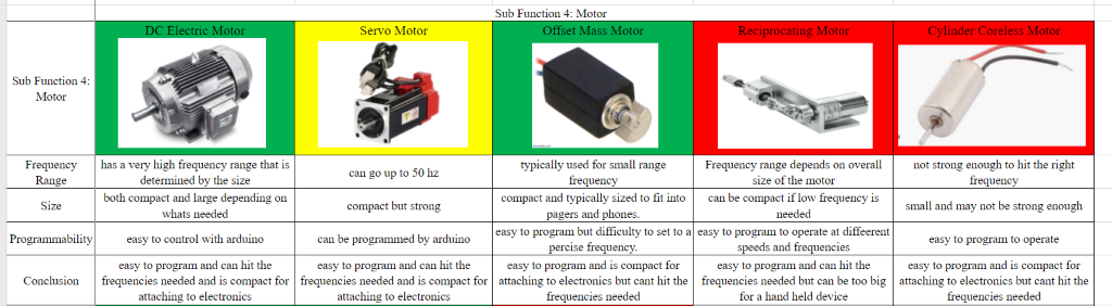
The fourth subfunction is the Motor.
Its solutions will be compared using the following criteria: Frequency Range,
Size, and Programmability.
Table 8: Excitation Subfunction Chart - Method of Vibration
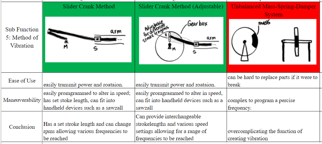
Method of Vibration is important
because different mechanisms have different variables that are considered. The
method that is applied will also affect the target vibration modes. Its
solutions will be compared using the following criteria: Ease of Use and
Maneuverability.
Table 9: Excitation Subfunction Chart - Arm Extension

Arm Extension allows the machine to
reach into the higher points of the tree. Its solutions are evaluated with the
following criteria: Weight, Cost, Maneuverability, and Safety
Function #2: COLLECTION
Table 10: Collection Morphological Chart
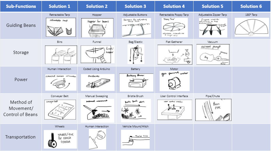
The Collection function is broken down
into five sub-functions: Guiding Beans, Storage, Power, Method of Movement/Control
of Beans, and Transportation.
Table 11: Collection Subfunction Chart - Guiding Beans
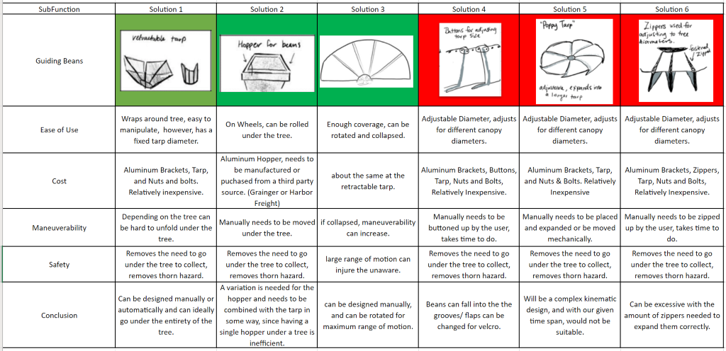
Guiding the beans requires that there be
a location for beans to fall and allows for the guidance of the beans to the
next step of the process. Its solutions will be evaluated through the following
criteria: Ease of Use, Cost, Maneuverability, and Safety.
Table 12: Collection Subfunction Chart - Storage
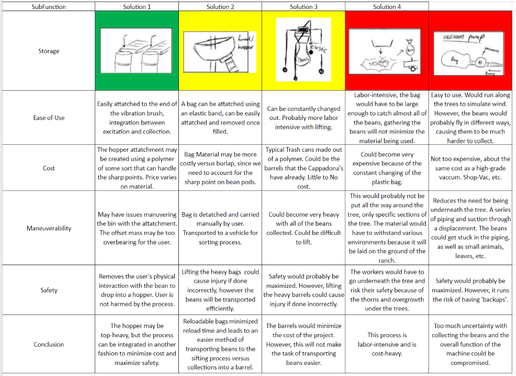
Storage of the beans is the last
step of the system. With the guidance of the bean to the storage selection, the
beans reach their destination where the user can use the beans for the next
step of their manufacturing process. Its solutions are evaluated with the
following criteria: Ease of Use, Cost, Maneuverability, and Safety.
Table 13: Collection Subfunction Chart - Power
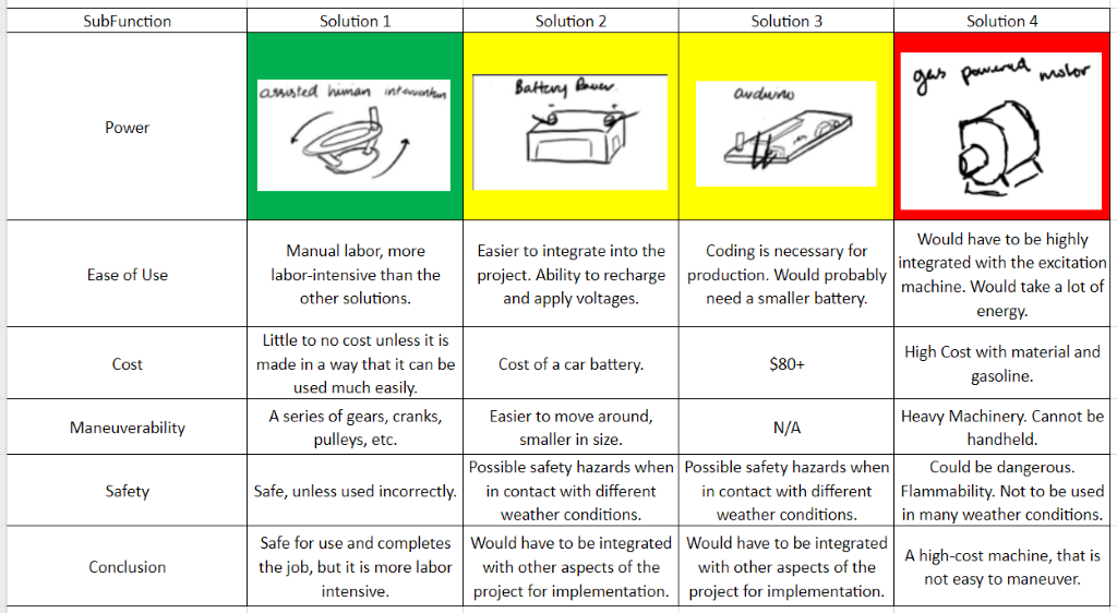
The third subfunction is Power. Its
solutions are evaluated with the following criteria: Ease of Use, Cost,
Maneuverability, and Safety.
Table 14: Collection Subfunction Chart - Method of Movement/Control of Beans
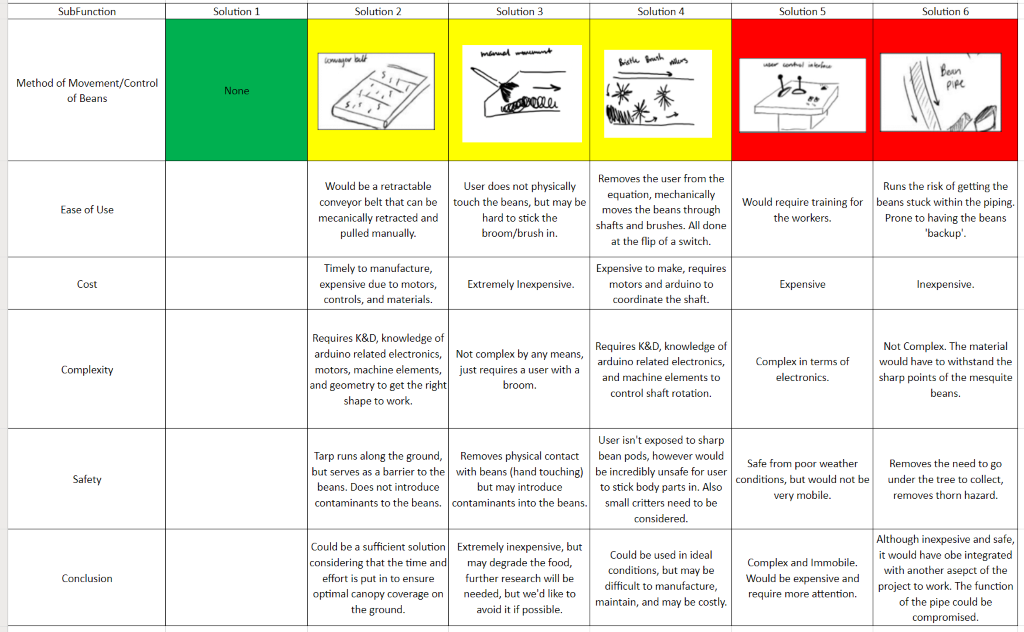
The fourth subfunction is Method of
Movement/Control of Beans. Its solutions are evaluated with the following
criteria: Ease of Use, Cost, Complexity, and Safety.
Table 15: Collection Subfunction Chart - Transportation
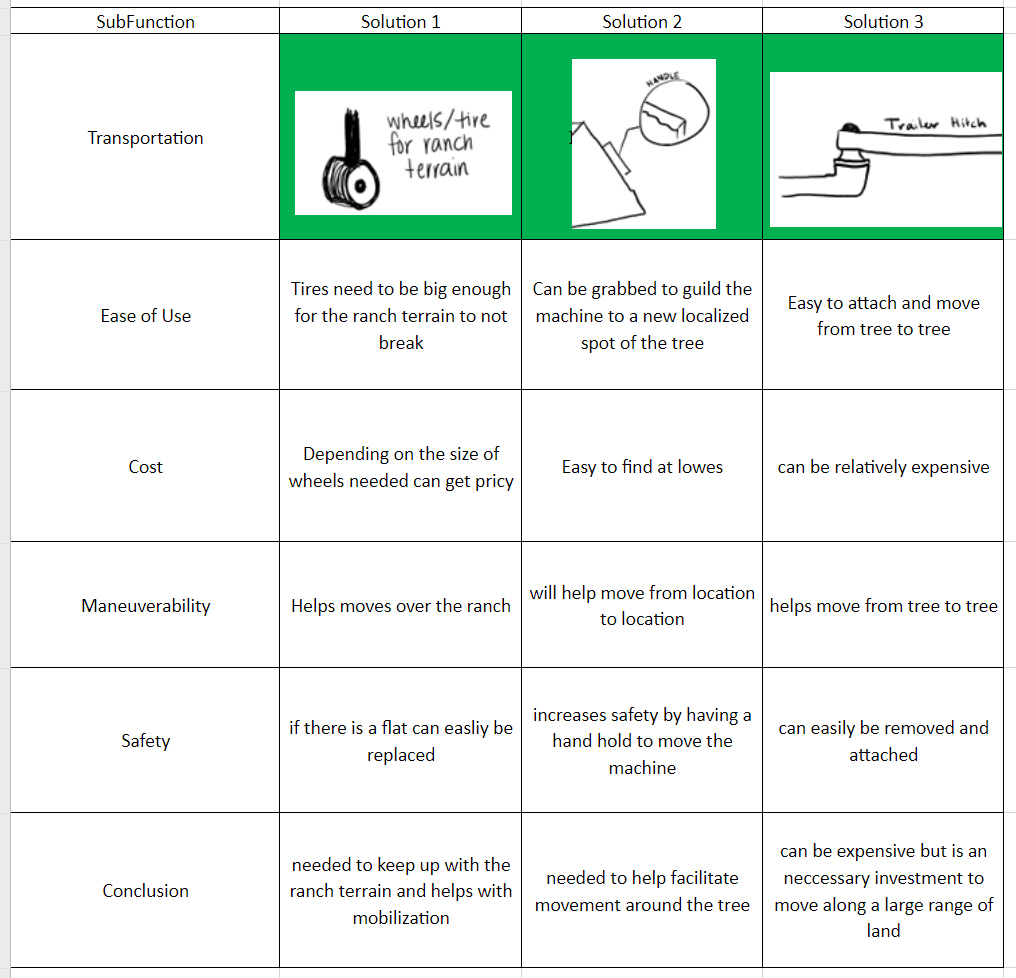
The fifth subfunction is
Transportation. Its solutions are evaluated with the following criteria: Ease
of Use, Cost, Maneuverability, and Safety.
CONCEPT VARIANTS
AND SELECTION PROCESS
Combining
all practical solutions would generate a factorial number of concept variants,
we had to be selective to find the best ones. This is our Concept Variant
Elimination Process:
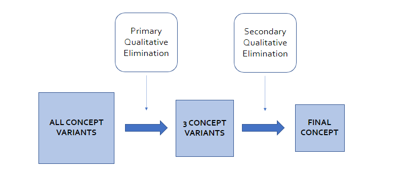
Figure 6:
Concept Variant Elimination Process
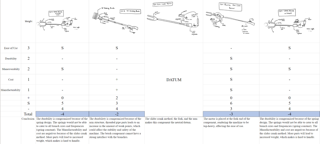
Function 1: EXCITATION
To begin our selection process, we set
up a datum to compare our concept variants against each other. The concept
variants are evaluated by the following criteria: Ease of Use (3 points), Durability
(2 points), Maneuverability (2 points), Cost (1 point), and Manufacturability
(1 point).
The three concept variants with the
highest scores will survive the Primary Qualitative Elimination and move
towards the Secondary Qualitative Elimination process.
Table 16: Primary Qualitative Elimination for Excitation
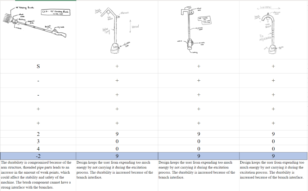
The top three concept variants are put
through a secondary qualitative elimination process and evaluated by the
following criteria: Method of Vibration (3 points), Arm Reach (2 points), and
Surface Contact with Branch (1 point).
Table 17: Secondary Qualitative Elimination for Excitation
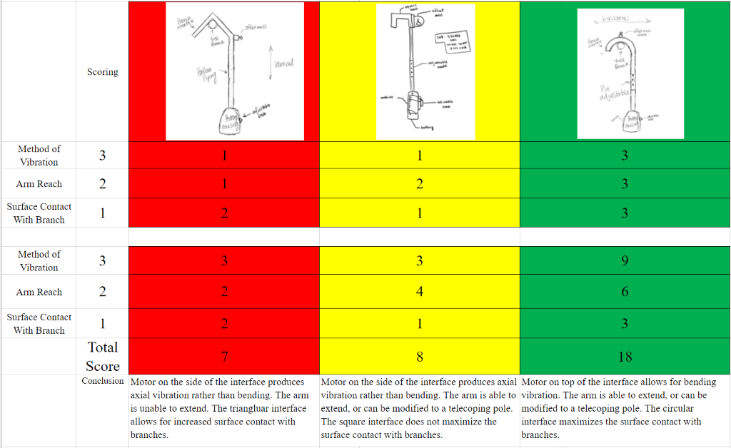
The highest scoring concept variant is
the circular, extending hook. This concept variant maximizes surface contact
with the branch, maximizes arm reach, and will produce the bending vibration of
the mesquite beans.
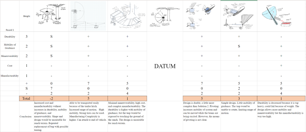
COLLECTION
To begin our selection process, we set
up a datum to compare our concept variants against each other. The concept
variants are evaluated by the following criteria: Durability (3 points),
Mobility of Guidance (2 points), Maneuverability (2 points), Cost (1 point),
and Manufacturability (1 point).
The three concept variants with the
highest scores will survive the Primary Qualitative Elimination and move
towards the Secondary Qualitative Elimination process.
Table 18: Primary Qualitative Elimination for Collection
The top three concept variants are put
through a secondary qualitative elimination process and evaluated by the
following criteria: Tarp Clearance/Range of Motion (3 points), Storage Size (2
points), and Weight (1 point).
Table 19: Secondary Qualitative Elimination for Collection
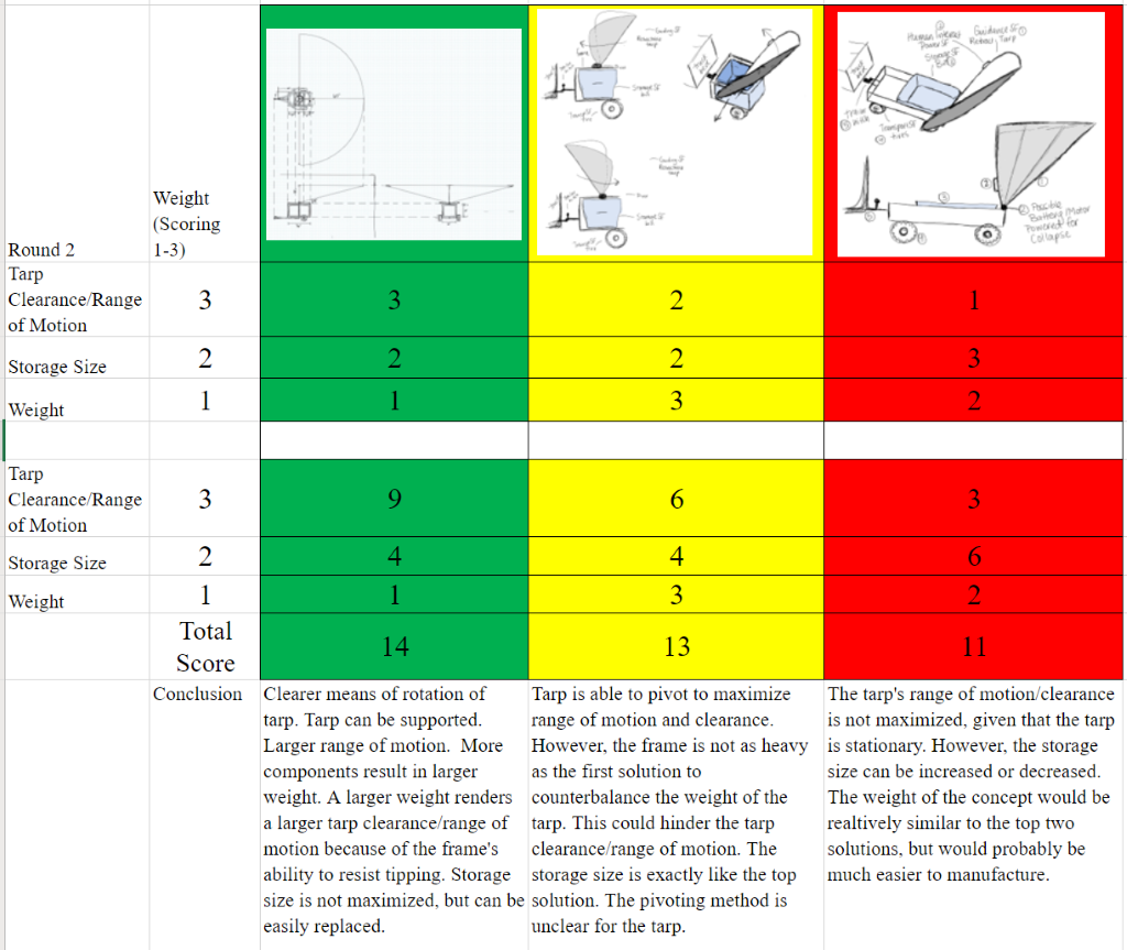
The highest scoring concept variant is
the Pivoting, Adjustable Height 180 Tarp. This concept variant maximizes tarp
clearance/range of motion, maximizes storage size, and will be heavy enough to
avoid tipping with the weight of the tarp.
FINAL CONCEPT(S)
After the
selection process we arrived at the Final Concepts for both Excitation and
Collection.
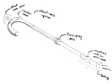
Figure 7: Circular Hook with Telescoping Pole – EXCITATION

Figure 8: Circular Hook with Telescoping Pole on Tree
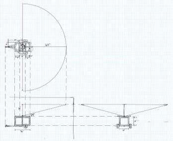
Figure 9: Pivoting 180 Degree, Adjustable Height – COLLECTION
The
embodiment process brings the final concept to life and requires using
engineering aspects to tackle technical questions. The design specifications of
the product itself are considered, and the final design is realized.
STRATEGIES AND
PRIORITIES
Starting
from our final concept, we identified the necessary analyses and engineering
work to realize the concept into a product.
TASK 1: DETERMINE
THE TYPE OF VIBRATION TO DROP THE MESQUITE BEANS
Before building, we needed to
determine the most optimal form of vibration to get the beans to fall. The
different forms of vibration, along with their respective stress
concentrations, are:

Figure 10: Forms of Vibration
The primary vibrational concepts used
for this project are Natural Frequency Resonance, and Mode Shapes.
· Natural Frequency: The frequency in which a system vibrates at after an initial
disturbance without external forces. [2] The natural frequency of a system can
be denoted as:
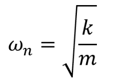
Equation 1:
General Natural Frequency Equation
where k is
the system’s stiffness and m is the system’s mass. The mesquite bean can be
modeled as a single degree of freedom mass-spring system, shown in Figure 11.
With SDOF systems, there is only one natural frequency within the system.
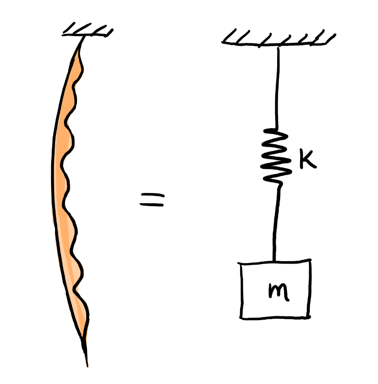
Figure 11: Mesquite Bean Modeled as a SDOF Mass-Spring System
· Resonance: When
the driving frequency of the system reaches/equals the system’s natural
frequency, resonance occurs. During resonance, the system is prone to breakage
or failure. Resonance can be denoted as:
![]()
Equation 2:
Evidence of Resonance
Where ωn is the natural frequency of the system. [2] The goal of the
vibrational aspect is to find the natural frequency of the mesquite bean to
match the driving frequency. From here, we should be able to reach resonance
and cause the mesquite bean to break off the branch.
· Mode shape: The shape that a system takes when
it is excited. For this project’s analyses, the mode shape number is denoted as
ⴖ.
For this analysis, we decided to use
Frequency Studies through the Finite Element Analysis method for multiple
Computer Aided Design (CAD) models. Through this study, we would be able to
determine the natural frequencies of the mesquite beans.
To view our Mesquite Bean Sample
Measurements, view here.
For the primary testing, we used
simple cylinders with dimensions similar to that of our mesquite bean sample
measurements. We completed the studies by treating our mesquite beans as clamped-free
cantilever beams. We used the following figures and equations for reference to
complete sanity checks for each type of
vibration and their first mode shape [2]:
·
AXIAL VIBRATION
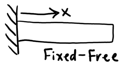
Figure 12: Axial Deformation Due to Axial Vibration
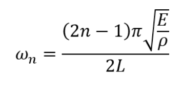
Equation 3: Natural Frequency Equation for Axial Vibration for the nth Mode Shape
· BENDING VIBRATION
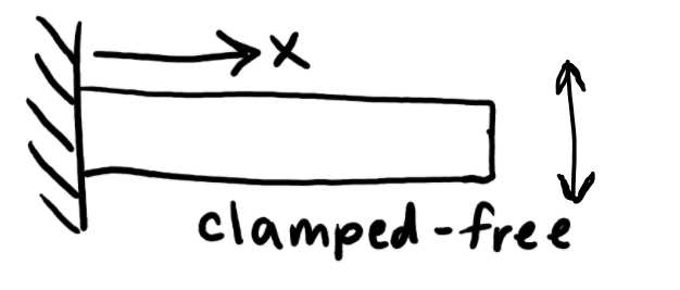
Figure 13: Perpendicular-To-X Deformation Due to Bending Vibration
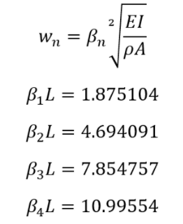
Equation 4: Natural Frequency Equation for Bending Vibration for the nth Mode Shape
· TORSIONAL VIBRATION
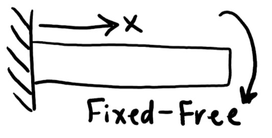
Figure 14: Deformation Due to Torsional Vibration
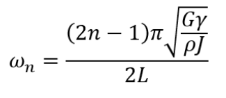
Equation 5: Natural Frequency Equation for Torsional Vibration for the nth Mode Shape
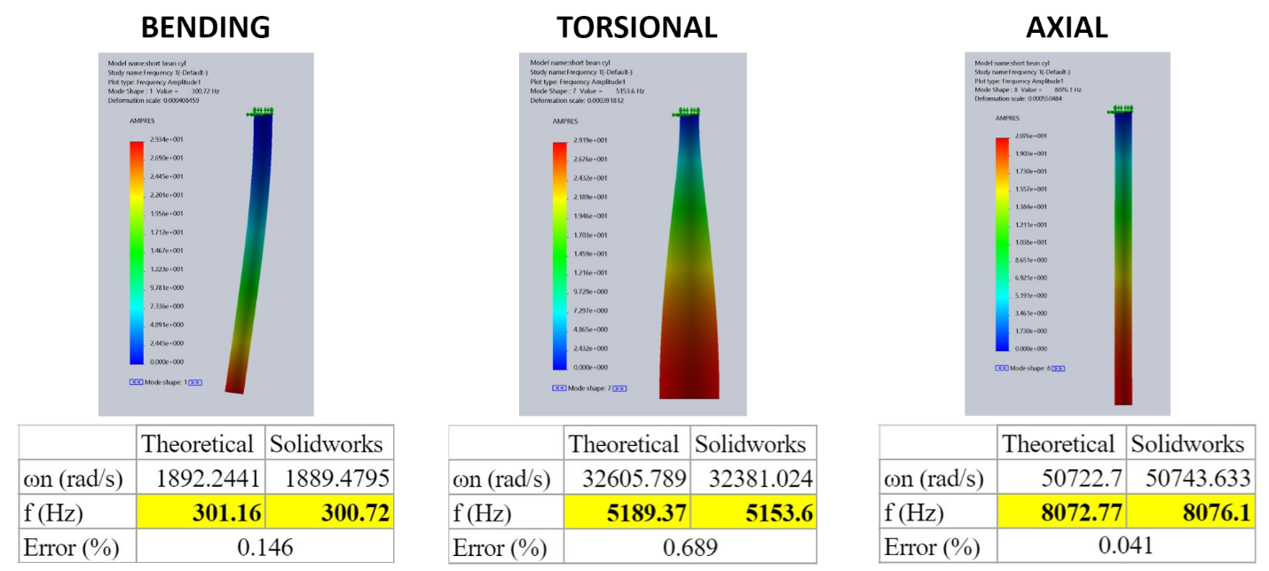
Figure 15: Sanity Checks for the Different Forms of Vibration
Our sanity
checks checked out with errors less than 1%. From here, we moved to increase
the complexity of our mesquite beans, as shown in Figures 16 and 17. We
completed the same FEA (Finite Element Analysis) process for the complex beans.
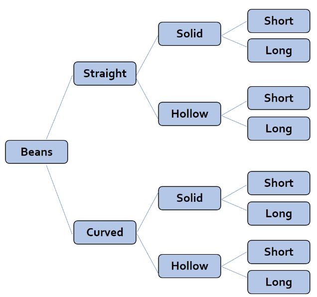
Figure 16: Different CAD Models Created
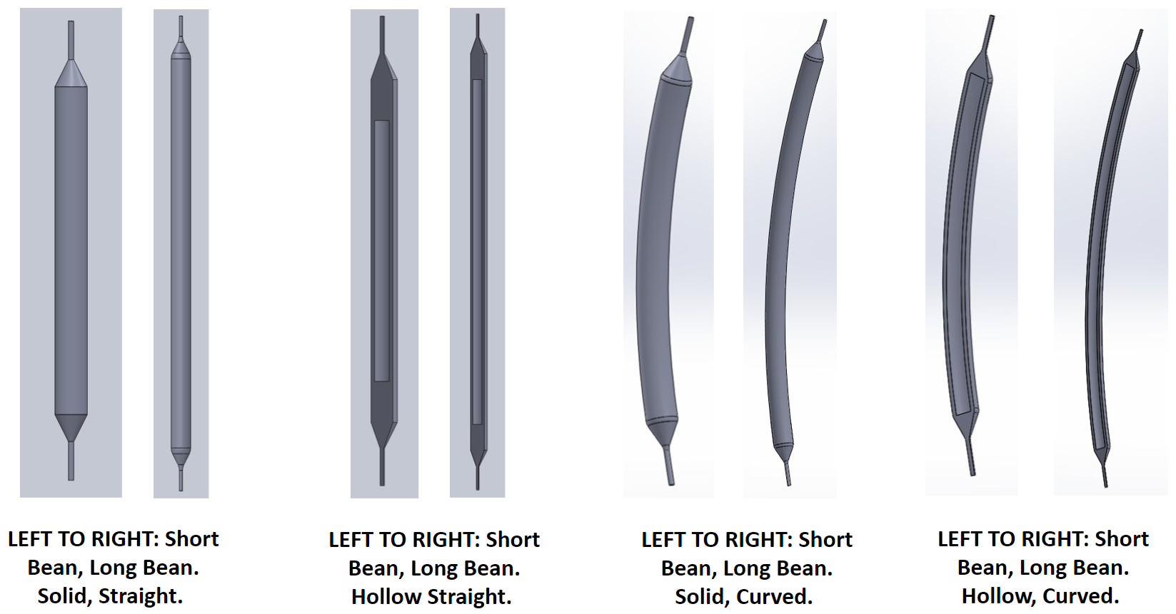
Figure 17: Increasing the Complexity of Mesquite Bean CAD Models
To view all
our Mesquite Bean CAD Models, view here.
To view the FEA Simulations on our
Mesquite Bean CAD Models, view here.
To view the Sanity Checks for the FEA
Simulations, view here.
By completing a comparative analysis
between our theoretical and experimental values, we determined the following:
· Bending Vibration is the prospective method of
vibration on its own.
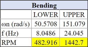
Figure 18:
Prospective Vibration and Its Corresponding Motor Speed
To view our full Mesquite Bean
Comparative Analysis, view here.
TASK 2: OFFSET
MASS/MOTOR SYSTEM
With knowledge
of Vibrations, an offset mass will be designed and utilized to create a radial
load. [2] Given the following equation:
![]()
Where FT
is the transmitted force, mo is the offset mass (typically the
center of mass of the offset mass), e is the mass eccentricity, and ωdr is the driving frequency. Our offset mass is designed with
the following template:
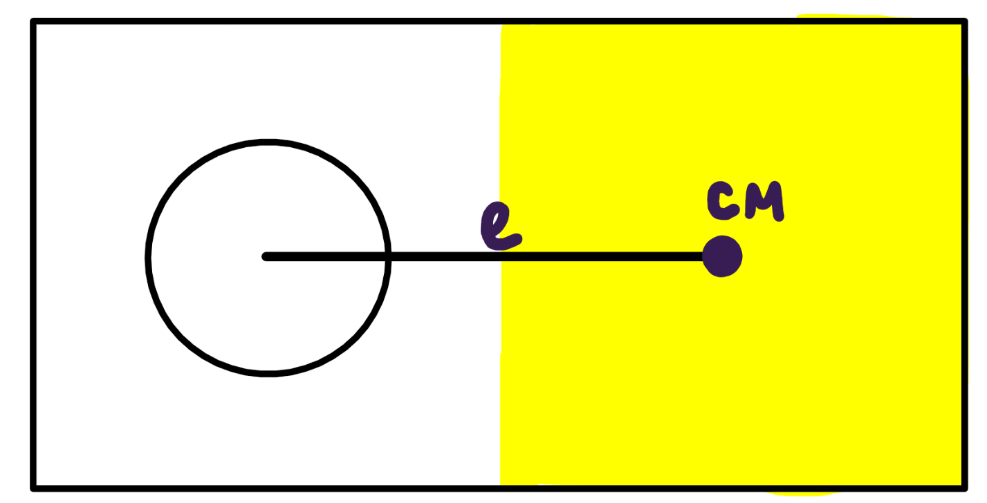
Figure 19:
Offset Mass Diagram/Template
The radial load generated by the
offset mass and the driving frequency will cause the vibration necessary to
excite the mesquite beans throughout the mesquite branch. The radial load will
depend on the orientation of the motor, such that:
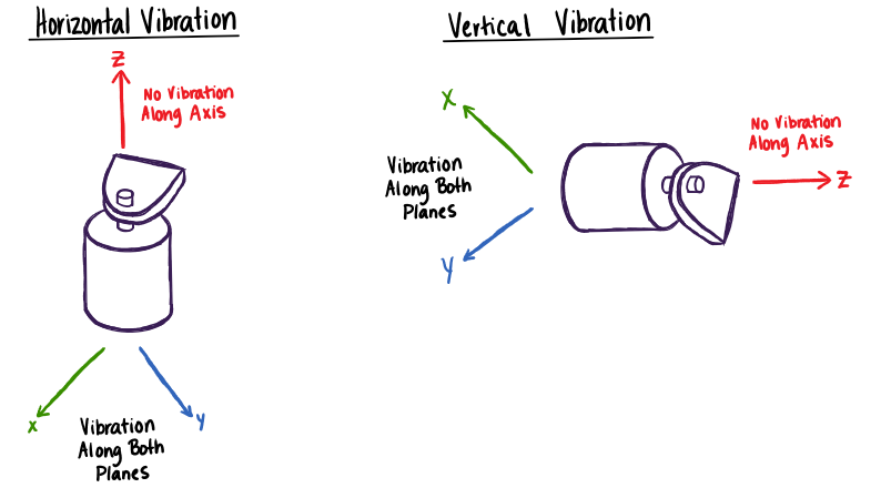
Figure 20:
Offset Mass/Motor Orientations and Their Respective Vibrations
Horizontal vibration will facilitate
bending and torsional vibrations, while vertical vibration will facilitate
axial vibration. [1] Based on this information, we decided to place the motor
upright to facilitate the bending vibration necessary to drop the mesquite
beans.
TASK 3: BUILD OUR
PROTOTYPES ON SOLIDWORKS

Figure 21:
Excitation - SolidWorks Prototype
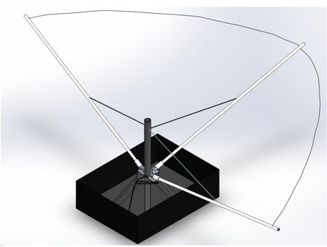
Figure 22:
Collection - SolidWorks Prototype
TASK 4: COMPILE A
MATERIAL LIST
To view our Material List, view here.
TASK 5: BUILD OUR
CIRCUIT
Our circuit utilizes an Arduino UNO, connection
wires, a potentiometer, a 400KV DC Brushless Motor, a Speed Controller, and a
rechargeable battery. This circuit will be used to operate the DC Brushless
Motor to create a radial load given by the offset mass.
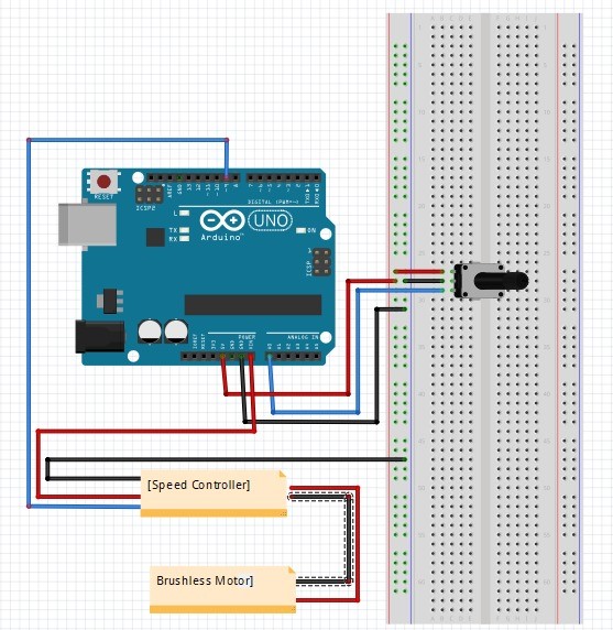
Figure 23:
Our Theoretical Circuit
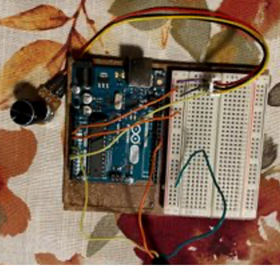
Figure 24:
Our Physical Circuit
TASK 6: DESIGNING
OUR MOTOR MOUNT

Click on the icon above to see the
Design Process of the Motor Mount!
TASK 7: MANUFACTURING
OUR PROTOTYPES
EXCITATION
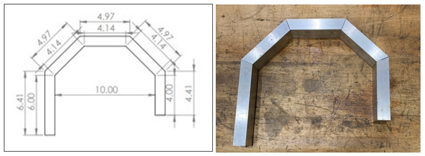
Figure 25:
Excitation Hook - From Idea to Reality

Figure 26: Carlos and Our Assembled Excitation Hook

Click on the icon above to see the
Steps to Use Excitation!
COLLECTION
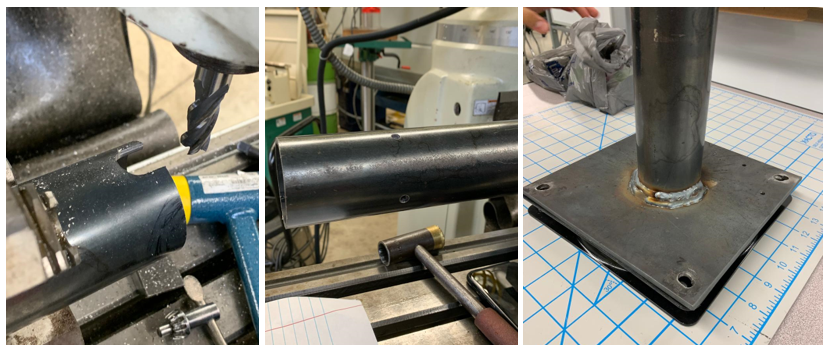
Figure 27: Milling and Welding Our Center Shaft
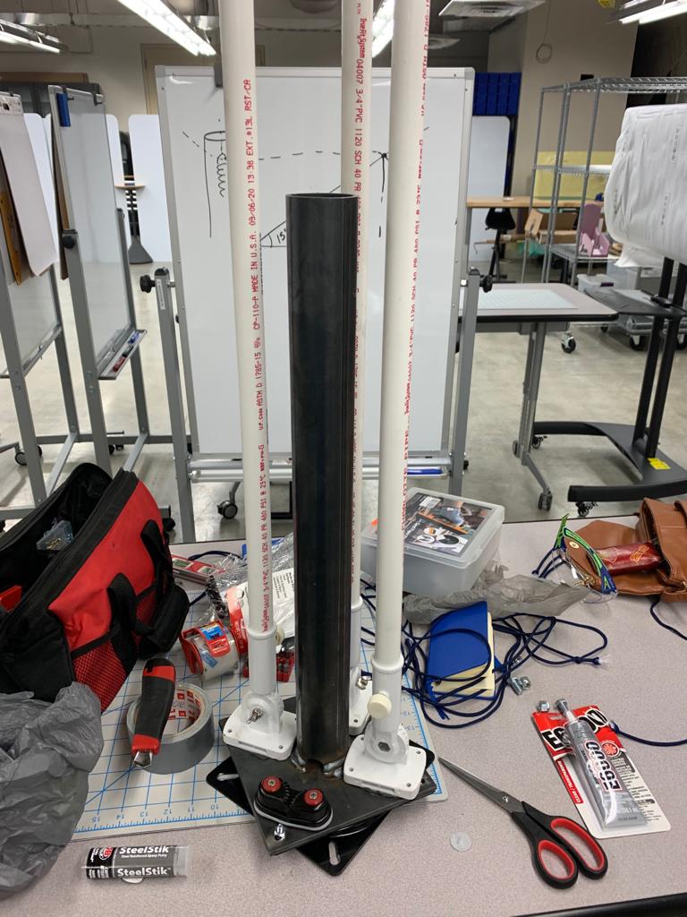
Figure 28: Partial Shaft/Swivel Assembly
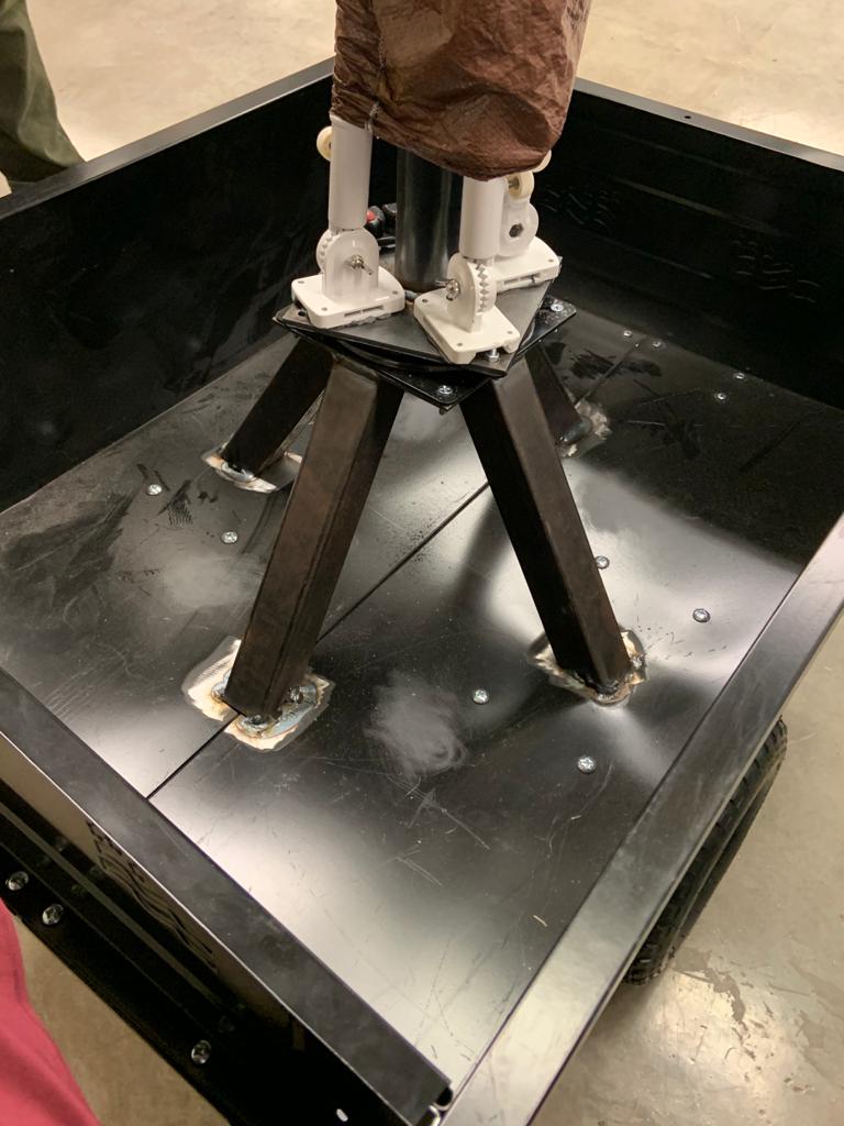
Figure 29: Frame/Cart Weldments
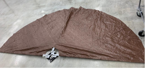
Figure 30: PVC/Tarp Assembly

Click the icon above to see our Collection
Tarp Swivel and Retraction!

Click the icon above to see the Steps to Use
Collection!

Figure 31: Both Excitation and Collection in Use
In
this final sub-process, the final design is tested, evaluated, and optimized so
that it can be used to effectively solve the problem identified. After testing
and validation, the final product can be directly led to a higher level of
production.
EXPERIMENT 1
Our goal for
this experiment was to test the vibrational frequencies emitted by the motor with
its off-set mass. Our goal was to simulate a high and low bending frequency of 24.045
Hz (1442.7 RPM) and at least 8.0486 Hz (482.916 RPM) respectively at the end of
the mesquite branch where the beans would naturally grow and develop during
harvesting season.
For our
first experiment, instead of following the chosen design of a hook, we attached
our motor to the tree with a belt to get a closer contact with the tree. This
would provide the least amount of dissipation caused by a branch interface.
Because we were past the bean season, measuring the levels of vibration where
the beans would naturally grow was the next best solution.
To view the
full testing protocol of this experiment, view here.
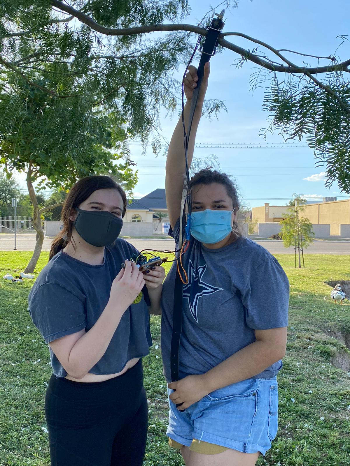
Figure 32: Alexandra and Stephanie holding the circuit/motor assembly for testing

Click the icon above to see our
assembly exciting the leaves of a mesquite tree!

Figure 33: Phone Used as an Accelerometer for Testing Purposes
We used our cell
phone as a means of recording our data. The app used was called phyphox, which
utilizes the accelerometer within a smartphone to measure the acceleration of
the vibrations transmitted to the end of the branches.

Figure 34:
phyphox - The application used to obtain our vibrational data
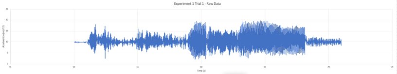
Figure 35: Acceleration vs Time Obtained from Experiment 1
The raw data
collected through this experiment allowed us to create an acceleration vs time graph. Within this
data, one can see the lower peaks in which there is minimal excitation and one
can see the higher peaks that represent the approach to resonance at that
location on the branch of the tree.
With a
signal like the one shown in Figure 31, the approach to this would be to apply a
Fourier analysis to convert the signal from its time domain to the frequency
domain. From there, the dynamic response of the mesquite bean would be
obtained.
After
further analysis of the experiments data, we noticed that by adding the cell
phone to the end of the branch would make a significant difference in the data
we wished to collect. This would change the problem from a cantilever beam to
one with a weight at the end of it therefore making the experimental data
invalid.
EXPERIMENT 2
For the second experiment, our purpose was to test the concept further by simulating the drop of a
mesquite bean due to excitation. However, since the harvesting season had already passed, we looked to an alternative and used rubber
bands simulate the mesquite bean stem being attached to the tree.
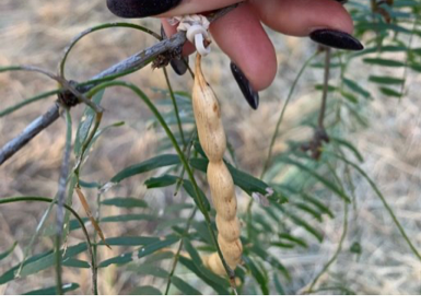
Figure 36: Mesquite Bean Suspended onto Branch by Rubber Band
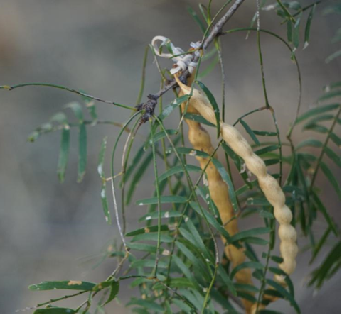
Figure 37:
Image Showing the Mesquite Beans Suspended on a Branch with Rubber Bands
We were
going to replicate the protocol in Experiment 1, but our motor began to
malfunction due to faulty wiring and completely stop working. We were unable to
complete further testing because finding and ordering a new motor was
necessary. However, if our motor had not given out, the vibrational frequency
transmitted from the motor to the bean would have been measured and collected by
analyzing a video of the vibrations in the bean as it fell shot by shot.
Experiment 2 would have provided us with important data which would have confirmed
our FEA analysis on the bending frequencies.

Click the icon above to see our motor
setup for Experiment 2. You will be able to see the motor malfunction.
[1] AB-027 :
Eccentric Mass Parameters For Vibration Motors - Application Notes. (n.d.).
Retrieved March 21, 2020, from https://www.precisionmicrodrives.com/content/ab-027-eccentric-mass-parameters-for-vibration-motors/
[2] Inman,
D. J. (2014). Engineering vibration. Boston: Pearson.
[3] Lesson
2: Problem formulation. (n.d.). Retrieved November 27, 2020, from
http://betterthesis.dk/getting-started/type-of-study . University of Southern
Denmark Library and the Unit for health promotion research. University of
Copenhagen, Department of International Health and Faculty Library of Natural
and Health Sciences
[4] Problem Identification.
(2019, January 02). Retrieved November 27, 2020, from
https://www.cdc.gov/policy/polaris/policyprocess/problem_identification.html
This is a
summary of important Senior Design files, click on each to open in a different
window.
SDI
MIDTERM
FINAL
SDII
REVIEWS
MIDTERM
FINAL