UTRGV / COLLEGE
OF ENGINEERING AND COMPUTER SCIENCE / MECHANICAL ENGINEERING DEPARTMENT
TEAM 1: REDESIGN OF A FILTER SYSTEM FOR INDUSTRIAL
MACHINING FLUIDS
(Design Process Page)

|
SDI
Students (L-R) |
· Karla Mariel Morales · Julio Deleon · Ramon Sanchez · Marissa Sandoval |
|
Faculty
Advisor(s) |
· Martin Johansson · Mostafa Malki |
|
Course
Instructors |
· Dr. Noe Vargas Hernandez · Mr. Greg Potter |
Back to the PROJECT
MAIN PAGE.
During
Senior Design we followed a design process
Problem ID
Problem Formulation
Conceptual
Design
POG
Our preliminary idea is to use a
combination of different sensors that could foresee when the mesh filter is about
to fail or need of service which if not addressed at the appropriate moment can
lead to making the filtration machine come to a complete stop. Next would be
investigating and improving the signal response of the coolant/fluid leveling
sensor system, which sometimes causes inaccurate readings due to some
coolants/fluids making foam during the filtration process. And if not addressed
this can lead to using excessive amount of filtration paper which tends to be
expensive.
VOA
When compared to the competitors, our product offers
affordability, ease of use and efficiency.
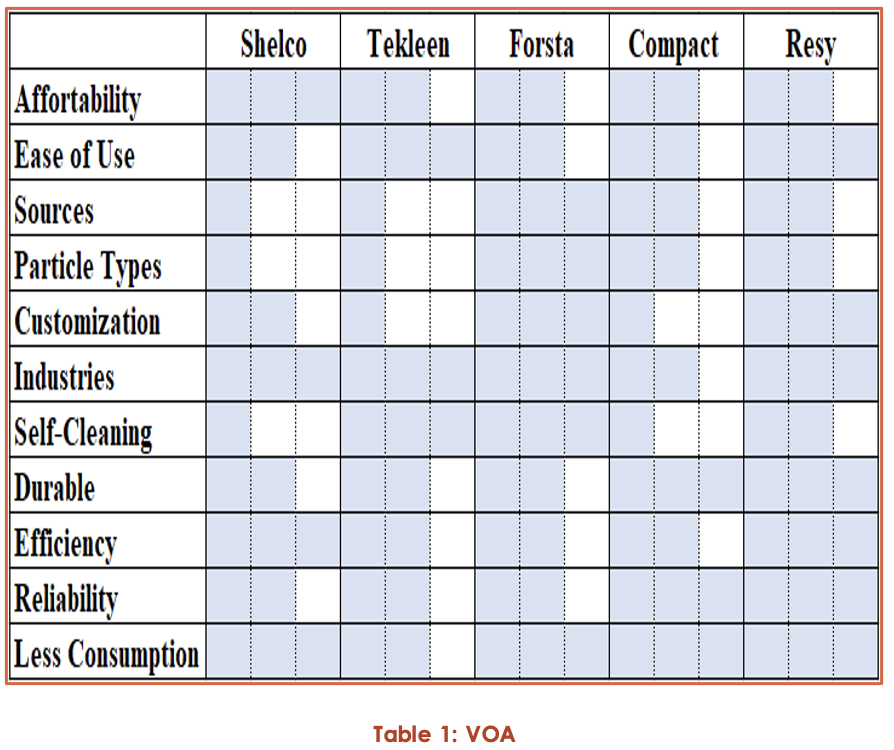
1. Affordability:
Our product is affordable to the companies and users.
2. Ease
of use: The function of the filter system will be simple in
order to allow the user to fully understand how to utilize the
machinery. There would also be an improvement in the aesthetics of the filter
machine by using meaningful tactics in the design to ensure we grab the user’s
attention.
3. Sources:
The filtering machine is designed to filter different type of sources.
4. Particle
Types: The filtering machine is designed to increase the efficiency in removing
various types of particles from the different materials.
5. Customization:
The design of the filter system is based on meeting the needs of the user.
6. Industries:
There are various industries that utilize and rely on the Resy
Filtering System.
7. Self-Cleaning:
The filtering machine is designed to self-clean and requires low maintenance.
8. Durable:
It is a durable product since it requires low maintenance.
9. Efficiency:
The product is very efficient in removing any particles by using the filtering
system.
10.
Reliability: It is a reliable product since
it is very efficient and functions properly.
11.
Less Consumption: The design of the filtering
system will allow for the product to decrease the amount of filter paper
consumption.
BACKGROUND RESEARCH
Filters have been a
crucial part of our human history. Believe it or not, ancient civilizations
used a variety of techniques to filter out unwanted substances/impurities for
things like drinking water. The earliest record of how humans used filters, dates back to around 500 B.C. where the Greek scientist
Hippocrates invented the so-called Hippocratic sleeve, which consisted of a
simple cloth back filter. After that there's records of the Egyptian
civilization at 400 A.D. using a variety of methods to eliminate harmful
bacteria from there drinking water, like I mentioned previously they used
several techniques such as boiling the water, heating it in the sun, or
submerged a hot iron into it. They also filtered impurities from their water by
sifting it through sand and gravel. And obviously as time went on so did the
innovation of humans, discovering filtration methods of separating the salt
from sea water to more complex things like being able to purify contaminated
water with the method of chlorination in the mid 19th Century. Now
currently with modern technology, humans have pushed the boundaries of
filtration towards the sky, from coffee ground bean filters to filtering metal
cuttings from the coolant that is used in machinery.
Furthermore, there is
an abundant amount of filtrations systems. All of them having their specific
area of filtering for example, the method in which how they filter, different
types of filtering material, and what type of objects/impurities the filtration
system will filter. With this is mine, the team has collaborated in defining
these different things and has made them into various categories which will
give an insight to these filtrations systems.
First category: Filtration
Methods
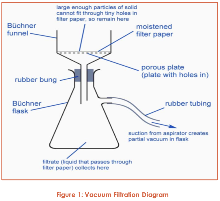
Vacuum Filtration
First and foremost,
the primary purpose of this method of filtration device is to distinguish
solids from liquids. The key benefit of this method of filtration is that it
incorporates negative pressure at the filtrate outlet. There are two distinct
types of filtering; sporadic filtration, which is ideal for thin solutions, and
constantly working filtration, which is optimal for treating viscous impure
powders.
A mechanically
pressed filter has been produced in order to produce a filter residue with a
low moisture content. A basic filter press is made by separating the container
into upper and lower chambers using a filter medium. The suspension is applied
to the upper chamber and reaches the lower chamber under strain through the
filter medium, forming a filtrate, with the rigid particles stuck on the filter
medium's surface forming a filter residue (or filter cake).
The filter residue
layer on the surface region of the filter medium steadily thickens during the
filtration process, raising the resistance of the material flowing through the
filter residue layer and reducing the filtration speed. Filtration is halted,
the filter residue is discarded, and the filter medium is regenerated to
complete a filtration cycle when the filter chamber is loaded with filter residue,
or the filtration speed is too slow.
To conquer the
resistance, the liquid must flow between the filter cake layer and the filter
medium, which requires a pressure gap on both sides of the filter medium, which
is the guiding force for filtration. While raising the pressure differential
will speed up filtration, the particles deformed after being pressed are more
likely to block the pores of the filter medium when the pressure is strong,
resulting in slowed filtration. Slag layer filtration, deep filtration, and
sieve filtration are used to filter the suspension. The term "filter
residue layer filtration" refers to the formation of the original filter
residue layer during the first step of filtration. Following that, the filter
residue layer performs a vital function in filtration. Both large and small
particles are trapped during this time; deep filtration indicates the filter
medium is dense and the suspension includes both large and small particles.
There are less stable objects, because the particles
are smaller than the filter medium's pores. The solid particles trapped by the
filter are larger than the pores of the filter medium, and the inside of the
filter medium does not adsorb the solid particles after they have been
filtered; the sieve filter is the solid particles trapped by the filter are
larger than the pores of the filter medium, and the inside of the filter medium
does not adsorb the solid particles after they have been filtered. The coarse
impurities in sewage are filtered out using filtration systems such as a tumble
filter screen.
The three approaches
are often used concurrently or sequentially throughout the actual filtration
operation. The filtration speed determines the filter's processing power. The
pores of the filtered filter residue layer are reasonably smooth while the solid
particles in the suspension are wide and standardized in size, and the filtrate
flows through the filter residue layer at a relatively high pace. The usage of
a coagulant to aggregate fine particles into larger agglomerates assists in the
speeding up of the filtration process. The filter applied in the upper part of
the filter medium is applied so that the filtration direction is consistent
with the direction of gravity, and the coarse particles are first settled,
which can reduce the clogging of the filter medium and the filter residue
layer; in the difficult-to-filter suspension ( If the solid particles settle
quickly), the filter applied in the upper part of the filter medium is applied
so that the filtration direction is consistent with the direction of gravity,
and the coarse particles are first settled, which can reduce the clogging of
the filter The filtration method can be sped up with these steps.
(The principle of vacuum filtration[Hawach Scientific])
Centrifugal Filtration
Antonin Prandtl is
credited with inventing this method of filtration device in 1864, which was
used to isolate milk and cream on a wide scale. Later, Swiss physician and
biologist Friedrich Miecher exposed him to research
labs for the first time. Furthermore, centrifugal separators are propelled by
the centrifugation method. Centrifugation separates ions from a solution by
using centrifugal energy. This method is usually used to isolate two immiscible
liquids in a solution.
An inlet, exhaust, and separator are also used
in the centrifugal separator. The combination of liquid and strong, solid and
liquid, or gas and solid is poured through the separator's cone-shaped
operating apparatus. The separator induces a revolving vortex, which enables
solids to be filtered from liquids. The solids that have been removed are
deposited at the bottom of the separator and purged. The contaminant and
high-density liquid flow out of the separator, while the low-density portion
stays inside. Since water is one of the denser substances, it passes outside
and is drained into an outlet. Lower density fluids, such as gasoline, will, on
the other side, stay at the core of the vortex. The extracted oil can be
quickly retrieved from the separator's suction orifice.
(The
principle of vacuum filtration. (2018, September 06). Retrieved February 27,
2021, from https://www.vacuumfiltrations.com/the-principle-of-vacuum-filtration/)
Also, centrifugal separators are available in different designs
and capacities. Depending on their designs, they are utilized in different ways
across various industries. Here are some applications of the filtration system.
·
Pre-Filtration:
The centrifugal separator helps improve the efficiency of filtration as well as
minimize liquid loss when it is used for pre-filtration. This pre-filtration
helps users save on expensive water treatment solutions.
·
Protecting
Heat Exchangers: They help protect heat exchangers effectively against fouling.
Centrifugal separators can remove scale and suspended grit easily.
·
Protecting
Spray Nozzles: Centrifugal separators are also used for protecting spray
nozzles and small orifices in various industrial applications. How? These
separators help remove solids that clog the nozzles of the spray. This, in
turn, helps reduce the wear and tear of the nozzle, as well as avoid its
regular replacement.
·
Reducing
Industrial Waste: As known centrifugal liquid separators are designed to remove
solids from a liquid. This becomes advantageous in case of applications, where
the disposal costs are high, or where recovery of high solids is mandatory.
This also helps improve the life of seals.
(Centrifugal separators
[Cannon, D., & Cannon, P.])
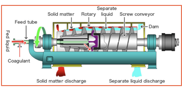
Figure
2: Centrifugal Separator Diagram
The disparity in
specific gravity between the liquid and the solid being filtered defines the
effectiveness of centrifugal separation. If the gap is high, the separation
efficiency can boost. The particle size has an effect on
separation efficiency. The visibility requirement for most separators is set at
40 microns.
Apart from being used in a
number of industrial applications, there are many drawbacks to utilizing
this form of filtration device, as well as several applications in which it is
used.
·
Maintenance Free: The centrifugal separator is largely
maintenance-free owing to the absence of moving parts or other components. It
is fitted with an automatic purge valve designed to flush the debris and
contaminants automatically.
·
Minimal or No Downtime: This is another major advantage of
centrifugal separator water filters or centrifugal separators used in the
industrial process. As the filtration is performed by the spinning of a vortex,
there are no real filters involved. This means there will no accumulation of
debris in filters, and there will no breakdown due to this accumulation. Also,
there will no need to change the filters more often, as in the case of other
liquid separators.
·
Minimal Liquid Loss: Do you know there is a little liquid loss
by purging while using centrifugal separators than other filters! Typically,
the users have to bear major liquid loses when
cleaning sand media filters or automatic strainers.
·
High Efficiency: The efficiency of centrifugal separation is 98%
of 40 microns in a single pass. However, for centrifugal separator, this is 44
microns. This stands valid for solids at the gravity of 2.6 and water at 1.0.
·
Environmental Processes: A centrifugal separator is used in
various environmental processes for industrial and municipal wastewater
treatment. It is widely used for separating biomass and animal slurry from
water.
· Recycling: Water
impurities are one of the main concerns of various recycling plants. These
centrifugal separators are used for treatment and recovery processes at recycling
plants. They are widely used for recycling service water in various industrial
processes.
· Plastic and Chemical
Processes: In the chemical industry, water is used in various phases of
chemical manufacturing. Various types of byproducts are generated during
chemical processes which may get mixed with water, thereby polluting the water
stream. The industrial centrifugal filters help avoid contamination of water
streams and recover intermediate or end products during the process.
Centrifugal separators are also used during plastic manufacturing. They find
great applications during PP, HDPE, and PVC polymer production. Similarly,
these filters are used in minerals and ores production, pharmaceutical and
biotechnology sectors, and during the production of non-fossil fuels, among
others.
· Food and Beverage
Production: This industry uses a lot of water and also
releases byproducts during various production processes. This is where
centrifugal separators can help. They are used during the processing and
recovery of non-liquid food products, fruit and vegetable juice production,
wine and sugar processing, among others.
· Oleo-Chemistry:
Several byproducts are generated during the production of oleo-chemistry
derivatives. They can be easily filtered using centrifugal separators. These
separators are also used for refining edible vegetable oils. However, they are
not recommended to use during the refining of olive oil.
· Mineral Fuel and
Lubricating Oils: Industrial centrifugal filters are used for purification and
conditioning of fuels, purification of lubricating oils, and treatment and
recovery of various fuel oils. They are also used for the treatment of
slop-oils from lagoons or refineries or bilge water.
· Animal-based
Products: The meat and fish processing create lots of useful and non-useful
byproducts. The centrifugal separators are used for the treatment of byproducts
from meat and fish processing industries.
(Centrifugal separators [Cannon, D.,
& Cannon, P.])
Gravity Filtration
When it comes to extracting solid
impurities from an organic liquid, gravity filtration is the tool of option. A
drying agent, an unnecessary side product, or a residual reactant may both be
impurities. While gravity filtration may be used to capture solid substance,
vacuum filtration is most often used since it is quicker. To remove insoluble
impurities from a hot fluid, a filtration technique known as "hot gravity
filtration" is used. Fluted filter paper and close attention to the
process are needed for hot filtrations in order to maintain the apparatus warm
yet protected so that the solvent does not evaporate. In organic chemistry
teaching laboratories, hot gravity filtrations are no longer used in standard
procedures for studies.
When scraping the solid precipitate to remove the filtrate, the
liquid, for further function or examination, a simple filtration under gravity
is used. Filter paper, filter funnel, retort stand to set and carry the funnel,
and a conical flask to collect the filtrate are the tools used for this
filtering technique.
(What is the difference between vacuum filtration and gravity
filtration? (2020, January 18). Retrieved February 28, 2021, from https://www.labrotovap.com/what-is-the-difference-between-vacuum-filtration-and-gravity-filtration/ )
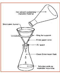
Figure 3.
Gravity Filtration Diagram
Cold Filtration
The cold filtration process involves using an ice bath to quickly
cool down the crystallization solution rather than setting it out to cool down
at room temperature. This process creates very small crystals, as opposed to
huge crystals, which can be produced by cooling the solution to room
temperature.
(Filtration. (2021, January 16). Retrieved February 28, 2021,
from https://en.wikipedia.org/wiki/Filtration )
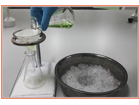
Figure 4.
Cold Filtration demonstration
Hot Filtration
The hot filtration method's primary
objective is to remove solids from a hot solution. This is achieved to avoid
the development of crystals in the filter funnel and any equipment that comes into contact with the solution. As a
consequence, the equipment and the solvent used are heated to avoid a
sudden drop in temperature, which would cause the solids in the funnel to
crystallize and obstruct the filtration method. The usage of a stemless filter
funnel is one of the most critical steps in avoiding the creation of crystals
in the funnel and maintaining successful hot filtration. Owing to the lack of a
stem in the filter funnel, the surface area of interaction between the solution
and the stem of the filter funnel reduces, preventing re-crystallization of the
solid in the funnel and negatively impacting the filtration mechanism.
(Filtration. (2021, January 16). Retrieved February 28, 2021,
from
https://en.wikipedia.org/wiki/Filtration )
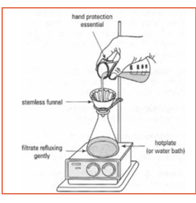
Figure 5. Hot
Filtration Diagram
Gravel Filtration & Multilayer Filtration
Gravel filtration is a deep-bed
filtration process that uses a multi-layer filtration device (filter gravel +
filter carbons). Water passes through multiple layers of filter content with
increasing fineness in the direction of filtration through multi-layer
filtration. Based on the size of the soil, it is agglomerated in the different
layers of the filter. Significant volumes of solids may be absorbed by
multi-layer filters. Gravel filtration, commonly known as multi-layer
filtration, is used in combination with flocculation to filter river water.
Filtration is often followed by a sedimentation stage as the first phase step
in these situations. Back-flushing is used to disinfect gravel and multi-layer
filters on a daily basis.
Furthermore, depth filters
(Sutherland, 2011) are porous filtering mediums made up of cellulose fibers and
inorganic absorbents that are used in multi-layer filtration. They can maintain
pollutants through the thickness as well as on the surface during liquid
filtration, unlike surface filtration. In a common medium, these hybrid systems
incorporate two distinct separation concepts and technologies. Filtration by
particle rejection is accomplished by creating an intricate mesh in which a
practical inorganic particle performs selective adsorption. Separation can be
increased still further by adding other additives to the network, such as
charged polyelectrolytes (Dizge et al., 2011). A
cationic polymer that adsorbs the typical negatively charged dissolved
pollutants in a far smaller pore size than the normal pore size may be added to
the medium. However, most depth filtration studies in the literature have
concentrated on membrane separation modeling (Polyakov, 2008, 2009; Sutherland,
2011; Kuhn and Briesen, 2016; Bedrikovetsky
et al., 2017; Goldrick et al., 2017); there are few
experimental studies optimizing depth style filter activity, especially in
terms of membrane structure.
Controlling filter structure/composition
and operating mode will tailor filtration efficiency in a variety of ways.
Dead-end filtration and cross-flow filtration are two
effective types of service, with the flow passing directly through the filter
in dead-end and tangential to the filter in cross-flow filtration (Liderfelt and Royce, 2018). These processes may also be
regulated using constant pressure or constant flow rate modes. In any case, the
non-constant parameter is tracked, and the reported parameters are used to
determine the degree of filter fouling or clogging (Iritani
et al., 2015; Goldrick et al., 2017). Modifying the
composition and configuration of filters may also improve filtration
efficiency. Multi-layer layered filters of different pore sizes stacked on top
of one another provide an easy way to separate cells or particles in a
sequential manner (Saefkow, 1995; Rijn, 1998).
Filtration was modeled on a multi-layered membrane system with each layer
having different pore sizes stacked on top of one another in a recent analysis by
Griffiths et al. (Griffiths et al., 2016). The effectiveness of a multi-layered
filter structure was investigated using a model that simulates particle
transport and filtration via a multi-layer structure. This model describes the
filter and gives recommendations for the number of filter layers, pore size in
each layer, and pore interconnectivity between layers.
Filtering bacteria using
multi-layered filters to increase bacterial capture has also been documented
(Koch, 1984). Through mechanically adding one sheet to another, which includes
a bacteria-destroying substance, the researchers hoped to achieve higher
bacteria rejection. A nano fiber film was added to the original layer of a
fibrous filter in another analysis (Wertz and Guimond,
2014). Filter media with a first layer adhered to it and a nanofiber layer
adhered to it had beneficial properties, such as improved dust keeping ability.
Despite the fact that
multi-layered filters are commonly used in industry, few studies have
systematically quantified their adsorption and filtration mechanisms, and still
fewer have characterized the impact of multi-layered structure on depth filter
efficiency. We generated multi-layered and single-layered filter systems using
the same amount of filter media in this analysis. Depth filter layer processing
was modeled after the papermaking method and checked for adsorption and
particle rejection. Using an advanced image technique and colloids and surface
principles, the adsorption and filtration processes behind the output of single
and multi-layered filters were studied in terms of chemical engineering and
internal filter structure.
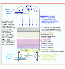
Figure 6. Gravel Filtration & Multilayer Filtration
Diagram
Mechanical filtration
In mechanical filtration, untreated
water passes through a mesh filter or cartridge that traps suspended particles
on the surface or within the filter. Within this type of filtration system,
there lays three most used techniques, which are Cartridge sediment filters,
Single media filters, and Multimedia filters.
The type of
mechanical filtration that will be suitable to your unique situation depends on
the amount and size of suspended solids in the water and the rate at which
water needs to be filtered. For example, a sand media filter has a faster
contaminant removal capacity than other types of filtration devices, but it is
not suitable for the removal of smaller particles. In contrast, cartridge
sediment filters with fiber or ceramic filter materials are made with a smaller
and more uniform pore size and can be more reliable in removing smaller
particles, but they are much slower and need more frequent replacement.
Types of
cartridge sediment filters
There are two basic types of sediment cartridges, depth-type and
pleated-type. Depth-type filters have graded densities with large openings (or
porosities) at the outermost surface of the filter, which decrease in size
toward the center core. These filters trap particles within the filter material
and are usually inexpensive. Pleated-type cartridge filters contain a rigid
polypropylene core for support and are made of one of the following materials:
· Pleated paper – These
filters are the most economical but are not reusable. They are sensitive to
water with low or high pH (less than 6.5 or greater than 8.5). Use them only
when the water contains no active bacteria, which may grow on the cellulose
portion of the filter. Water testing for pH and total coliform and E. colishould be conducted to assess whether your water is
suited for these types of filters.
· Pleated cotton and
polyester – These filters are generally considered the most versatile. They
combine the filtration ability of cotton with the strength of polyester. As long as the water pH is between 4 and 9, they can be
cleaned and reused several times.
· Pleated polyester and
polypropylene – These filters are the most expensive but can be repeatedly
rinsed and reused. However, since the fibers are smoother than the other filter
materials, they are not quite as effective at retaining particles.
Pleated
cartridges have a high filtration surface region, allowing for faster
filtration. The filter collects particles on its outermost surface, causing a
filter cake to form, which improves filtration but delays water movement (or
speed of filtration). They can accommodate huge volumes of particulates and
turbidity without creating a drastic decrease in water pressure. While they are
initially more costly than depth-type cartridges, they are less expensive and
last longer in the long term.
Turbidity
is a measurement of water's relative purity. When a light is shined into a
water sample, it is an expression of the volume of light scattered by the
materials present in the water. The turbidity increases as the amount of
dispersed light increases. Clay, silt, thinly divided inorganic and organic
matter, bacteria, soluble colored organic compounds, and microscopic plants
(not recognizable to the naked eye) and other microscopic species all
contribute to the turbidity of water.
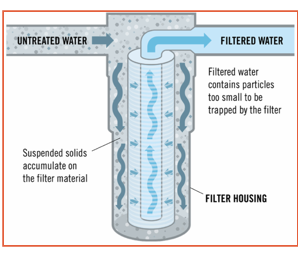
Figure 7. Mechanical Filtration Process
Water pressure forces water through
the media or fiber wraps through the inner cylinder in the sediment filtration
phase, where it is then free to pass through the water line. The medium
contains toxins and dissolved solids from the stream.
The pore space between media fibers
or granules can decide how many particles are kept. These filters come in a number of sizes and meshes, varying from fine to coarse.
The average pore size is reported on most filters, and the vendor scores them
based on the smallest particle they can trap. A 10-micron (one thousandth of a
millimeter) filter, for example, will capture particles with a diameter of 10
microns or greater. When shopping for filters, keep in mind that many are only
rated for particles 20 microns in diameter or larger. Clay (less than 2
microns) and certain silt particles (2.0-50 microns) smaller than 20 microns can not be effectively eliminated by filters with this
rating. They would, though, capture sand particles varying in size from 50
microns to 2 millimeters.
The cleaner the filter, the more
contaminants are trapped, and the filter must be adjusted more often. The
filter can quickly clog if the pore size of the filter material is too tiny, or
if the content of suspended solids in the untreated water is too high, causing
regular replacement. Suspended solids, on the other hand, can move through the
system if the pore size is too big.
When a fresh or replacement
cartridge is fitted, the water pressure into the filter is at its highest. A
filter cake forms when stuck content accumulates in the filter,
and may improve its efficiency by aiding in the filtration phase. Water
flow, on the other hand, would eventually decline as trapped fluid accumulates.
The filter cartridge can be washed or removed until the water flow becomes too
sluggish to use.
Single Filters and Multimedia Filters
Media filters consist of a tank, a
single filter medium, multiple filter layers, a support system, and an
underdrain. The bed depth of the filter medium is usually 24 to 36 inches and is
comprised of silica sand, aluminum silicate, and/or crushed anthracite (a hard,
compact variety of mineral coal). Usually a gravel
support system prevents the medium from being washed out of the device. Media
filters can be cleaned by backflushing and reused. Filters are rated by the
smallest particle sizes they remove. With a same sized tank, multimedia filters
have a greater filtering capacity than a single-media filters. Generally,
multimedia filters also operate at a higher flow rate and require less frequent
maintenance than single-media filters.
Here are some examples of how this filter is used and, one thing
to take notice is that media filters are point-of-entry (POE) devices that
treat water at its entry point into the home. Some common uses of media filters
are:
·
Media
filters remove particles that cause turbidity (cloudiness of water). These
filters can also be part of iron, manganese, and hydrogen sulfide removal after
they have been oxidized into solid particles via aeration, chlorination, ozonation,
or greensand filtration. See UGA Extension Bulletin 939, Circular 858-11, and
Circular 858-15 for explanations of these treatment systems.
·
A
media filter can be used as a prefilter when suspended solids in the source
water could reduce the effectiveness or service life of another primary
treatment device like ultraviolet light or chlorination units used to disinfect
water. If suspended solids are not removed prior to the UV device or
chlorination unit, the solids may shield microorganisms from the killing action
of light or chlorine and result in unsatisfactory treatment performance. See
UGA Extension Bulletin 1487, “Household Water Treatment: Disinfection Methods
and Devices.”
·
Prevention
of sediment build-up in washing machines, dishwashers and hot water heaters
Furthermore, a single media filter
operates by enabling untreated water to reach the filter tank under pressure
from the top and percolate through the medium, trapping any suspended solids.
At a significantly decreased strain, treated water escapes the system from the
bottom of the medium. Suspended solids settle on the media surface, creating a
filter cake, which helps in the filtering of fine particles but decreases water
movement over time. The multimedia filter operates in a similar manner, only
that the various levels of filter media are organized in order, with the
coarsest content at the top and the finest at the bottom. Bituminous
coal/plastic beads and anthracite coal/sand/garnet are two instances of
sequential media layering from the top.
At the bottom of the media bed is a
media support structure (usually gravel) and an underdrain. The media does not
wash through the underdrain because of the gravel support. Under heat, water
reaches the top of the tank and passes across the media layers. Suspended
solids are suspended by lower layers after passing through the top layer.
Multimedia filters, in comparison to single-media filters that capture
suspended particles at the top of the media column, trap particles throughout
the depth of the web. Multimedia filters, on the other hand, need less regular
maintenance than single-media filters. The interparticle pore space, which
specifies the size of suspended solid particles in untreated water that will be
filtered out, is defined by the particle size in the different media layers.
Granular Media filtration
Granular Media Filtration (GMF) is
the process of removing suspended or colloidal particles. For example, to
remove the suspended solids remaining after precipitation. By removing
particles of various sizes (from coarse sediment down to 10.0μm), it can reduce
turbidity and improve clarity. Filtration can protect the IX resin bed and
RO/NF membrane elements from particle contamination. Media filters have
different size exclusion levels, from 10 to 100 μm,
depending on the size of the particles to be removed. Generally, when the water
sludge density index is about 5, suspended and colloidal particles can be
removed by GMF, dead-angle MF and crossflow MF. For high-concentration
colloidal substances, coagulation and flocculation are required before media
filtration.
The granular multimedia filter has
a layered bed of anthracite (0.8-1.2 mm in size), sand (0.5-0.8 mm), garnet
(0.4-0.6 mm) and magnetite (0.3-0.4 mm) or other materials, such as As shown in Figure 2.4. The top
layer of the bed is composed of the lightest and coarsest graded material, such
as anthracite, while the heaviest, finest material, such as garnet or
magnetite, is the bottom layer. The middle layer is silica sand. The specific
gravity of anthracite is one-half of silica sand. The typical bed depth is 1 m.
The principle is "deep filtration"-larger particles are removed in
the top layer, and smaller particles are removed deeper in the filter medium,
that is, the entire bed acts as a filter, instead of the top few centimeters.
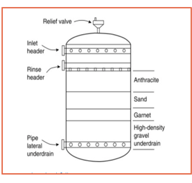
Figure 8 :
Granular filter
During use, water usually flows
from the top to the bottom under pressure. The typical service surface flow
rate (velocity/cross-sectional area of bed) for single media gravity and pressure
filters is 7–12 m/h, multimedia media gravity and pressure filters are 14–20
m/h, and 12–24 m/h is used for Upstream filter. The operation of the filter
must avoid channeling and "leakage" of suspended solids. Otherwise,
the reverse osmosis membrane will be soiled. There is a water level above the
bed (freeboard is 50-100%) to expand the bed during backwashing. Since
suspended solids will collect on the medium, regular cleaning (backwashing) is
required. The repelled particles form a layer on the surface of the media and
help to block the pores in the filter media, resulting in an increase in
pressure drop (ΔP). Generally, when ΔP reaches 1 bar, the filter will be
backwashed. During the backwashing process, the water flows in the opposite
direction. It enters the bed from the bottom and flows upward. This fluidizes
the bed and, together with the countercurrent flow, removes the sludge and
takes away the waste material. Depending on the temperature, the typical
backwash flow rate is 24–36 m/h, which is sufficient to expand the media bed by
at least 50%. The backwash cycle lasts 10-15 minutes, followed by a rinsing
cycle in which water is circulated in the downward flow direction for 5-10
minutes.
Second Category:
Filter Types
Filter paper
For good reasons, wire mesh and
wire mesh industrial filtration are commonly used in commercial and
industrial/OEM applications. In some industrial filtration applications, the
goal is to protect downstream components from particulate matter. In other
cases, a wire mesh filter can be used to separate or screen one substance from
another.
Whether your specific industrial
filtration application needs to remove harmful contaminants from fluids or air,
protect expensive process equipment, or just separate one material from
another. Bag dust collectors, cartridge dust collectors and dust filters are
usually made of synthetic media. Many filtration companies can create your
precise size filter and replace stainless steel wire mesh or wire mesh media to
achieve better fluidity and more efficient machine functions.
The flow rate in the sediment
filter and the separator has a large overlap between the sizes. For example, a
1" filter housing has a flow rate of 1-25 GPM, while a 1-1/2" filter
housing has a flow rate of 10-50 GPM. If your flow rate is within this range,
it is best to choose a smaller size to ensure that the centrifugal force is
sufficient to separate the sand from the water. This means that if you want a
flow rate of 20 GPM, a 1-inch filter housing will be more effective.
There are two different styles of elements, filters and
separators. They all work in the same way; the difference is that the separator
allows more sediment to accumulate before it needs to be removed. Our
"Understanding Sediment Filters and Separators" blog describes the
differences in more detail. 1.5 and 2 elements Depending on the size of the
housing, the appearance of the filter may vary. For the 1-inch housing, the
filter between the filter and the separator looks the same, while for the
1-1/2-inch and 2-inch housings, the filter has a shorter screening area and
keeps the filter part at the valve stem at the top, which provides space for
the accumulation of sediment at the bottom. The image shows a filter element on
the left and a separator element on the right for a 1-1/2" or 2"
housing.
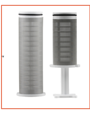
Figure 9: Filter and Seperator
element
Mesh
Material
Mesh fabric
is a barrier material made of connected strands. These strands can be made of
fiber, metal or any flexible material. The connection threads of the grid
produce a net-like network with many different uses and applications. Mesh
fabrics can be highly durable, strong and flexible. They are known and are
usually used in the case of liquids, air and fine particles that require
permeability.
The history of mesh fabrics can be traced back to 1888, when a
British textile factory owner introduced the concept of a clean, breathable
material that can withstand temperature changes into the product. Since the
yarn is knitted or woven together and has an open space between the yarn
strands, it is a superior material for clothing and fashion, and has been used
in clothing, wraps, gloves and scarves in the last century in the final
product. When wet or dry, the material has great adhesion (this only means that
the dye will not wipe off). The mesh is also easy to sew.
There are two main types of mesh materials, polyester and
stainless steel. The polyester mesh is made of non-corrosive materials and has
UV stability/weather resistance. The stainless-steel mesh is made of 316
stainless steel, which is non-corrosive and durable.
Stainless steel will better absorb sharp deposits and particles because they
will not tear the material. In the past, polyester was a more economical
choice, but this changed them and made it a very economical choice. As the
fibers are woven together, they create a very flexible, net-type finish that
has a tremendous range of end-uses. It can be used in so many industries,
including: the food industry; wastewater industry (separating waste and sludge
from water); hygiene and sanitary industry; pharmaceutical industry; the
medical industry (supporting internal organs and tissues); paper industry; and
the transportation industry.
Mesh
Material Sizes
Mesh fabrics can come in many different sizes and are clearly
numbered for understanding. Choosing the required mesh size depends on what
needs to be removed from the water. When talking about filtering, there are
different terms that define the size of the items to be removed. The equivalent
table below shows a comparison between different terms. The equivalence diagram
opening is the size of the space between the water and the material through
which the particles can pass. The number of openings in a square inch screen is
called the mesh size. The micron level is the distance between filter media. A
micron is one-millionth of a meter or one twenty-five thousandth of an inch.
This is described in more detail in "Water Filter-The Basis of Micron
Grade". When using a sediment filter or separator as a pre-filter for
other water filtration products, make sure that the mesh size is equal to the
larger micron level.
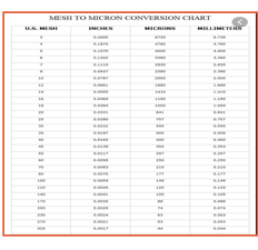
Figure 10: Equivalence Diagram
For example, a 4-mesh screen means
that there are 4 "squares" on a linear inch of the screen. A 100-mesh
screen only means that there are 100 openings on a linear inch, and so on. To
determine the grid size, count the number of rows of grid squares in one inch
of linear space measured. This will provide the grid size, which is the number
of openings per inch. Sometimes, the grid size may be refined to 18×16, which
is defined as 18 holes per 1 inch square and 16 rows of openings down. However,
the particle size of a mesh fabric is an indication of the size of the material
that can penetrate and pass through the mesh. For example, the particles
contained in a 6-mesh powder can pass through a 6-mesh sieve.
Third Category:
Coolant Types
Coolants are an
instrumental section of machining, together with grinding, milling, and
turning. They assist lengthening the devices lifestyles and grant a better
finish to machined components. Understanding the function and sorts of coolant
will assist you to pick out a coolant that is the proper for your machine and
operation. By exactly keeping the awareness degrees of your coolant, you
lengthen now not solely the lifestyles of the coolant however additionally your
equipment and machine.
These following
points are the things that the coolant helps provide.
·
Reducing and removing the heat build-up in the cutting zone and
workpiece
·
Provides lubrication to reduce friction between the tool and
removal of the chips
·
Flushes away chips and small abrasive particles from the work
area
·
Protects against corrosion
According to, https://www.firetrace.com/fire-protection-blog/importance-of-coolants
Furthermore, coolants are classified into four
groups and come in a number of formulations. Coolant
should be chosen based on its overall efficiency, which again should be
tailored to your machining application and materials. Here are the following
groups.
· Soluble Oils:
The most widely used of all water-soluble cutting
fluids, and an excellent option for general machining. The disadvantage is that
if the coolant sump is not properly maintained, they are susceptible to fungus
and bacteria microbiological growth.
· Synthetic Fluids:
Since they contain no mineral oil and refuse tramp
oil, these fluids are the cleanest of all cutting fluids. They do, however,
have the least amount of lubrication.
· Semi-synthetic Fluids:
They are thought to be the best of both worlds
because they contain less oil than emulsion-based fluids, have a less pungent
odor, and have many of the same lubricating properties. As a result, they can
be used for a wider variety of machining.
· Straight Oils:
These are non-water miscible and contain
lubricants such as vegetable oils, fats, and esters, as well as a mineral or
petroleum oil foundation. They provide the best lubrication but have the worst
cooling properties.
How Machine Coolant Systems Work
The coolant mixture
floods the work area during the machining process. Chips and particles are also
washed away from the work area during this operation. A sump at the bottom of
the unit absorbs the coolant. The coolant is recirculated to the work area
after being pumped out of the sump.
Coolant systems, both
central and single unit, must be tracked, maintained, and modified. Small
coolant systems, on the other hand, prefer to use less efficient filtration and
oil separation equipment than central systems. Smaller structures are often
more vulnerable to sudden changes in concretion levels and greater
fluctuations. As a result, small-system coolants must be more resistant to
contamination from metal shavings, tramp oils, and other materials. Not only
does coolant form play a role in extending coolant life, but proper coolant
management is even more important.
Coolant Concentration
Several issues will
arise if proper coolant concentration levels are not maintained. Low concentration
is the most common issue. If the coolant concentration falls below the minimum
ratio set by the machine coolant supplier, there is a chance of:
·
Machine and workpiece corrosion
·
Reduction in tool life
·
Bacterial growth
On the other hand, if the coolant concentration is
too high, it causes:
·
Lesser heat transfer
·
Foaming
·
Reduced lubrication
·
Wasted concentrate
·
Formation of residue that shortens tool life
·
Staining of machine and machined parts
·
Toxicity (skin irritation)
The coolant should be
tested at the start of each day to ensure that it is at an appropriate
concentration level. Hand refractometers are an excellent way to keep track of
cutting and grinding fluid concentrations on a regular basis. Evaporation,
splashing, misting, and drag out can cause machine coolant concentrations to
fluctuate by 5% to 20% per day. Keeping a daily log of concentration levels for
each unit allows you to see how the device works and how much concentration
levels fluctuate from day to day.
So again,
you will prolong the life of the coolant, the equipment, and the machine by
choosing the correct coolant for the type of machine and the metals being
machined, as well as preserving the concentration levels.
Fourth Category:
Control Systems
Energy efficiency in
industry is becoming increasingly important as energy prices rise and the value
of climate security grows. According to research conducted by Robert Bosch
GmbH, the coolant consumes on average 50% of the electrical energy used in
traditional metal cutting applications. As a result, the focus of this study is
on lowering the energy consumption of the coolant supply system.
Cooling, lubricating, flushing, and transporting
are the primary functions of the coolant. In a circulatory system, the coolant
is used and processed. The following functional units can be found in this
circuit: supply, return, washing, and cooling (Figure 11). After usage in the
machine tool, the contaminated coolant is returned to the cleaning device. In a
filter system, the pollution is isolated from the coolant, restoring the
necessary fluid cleanness rating. In addition, heat exchangers in a cooling
unit keep the coolant temperature stable. There are two types of circulation
systems: centralized and decentralized. Centralized systems are commonly
favored because they are more cost effective than decentralized systems.
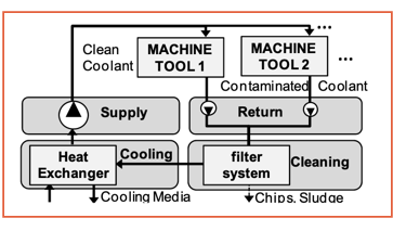
Figure 11. Functional units of a coolant
supply system
Various steps to
improve the energy efficiency of the coolant supply system have been developed
in recent years. A previous study conducted at Robert Bosch GmbH aimed to find
additional energy-saving potentials in state-of-the-art coolant facilities. As a
result, the energy efficiency of a number of
centralized coolant supply systems was assessed. Pumps are responsible for the majority of the energy used in the coolant system. Until
now, the primary focus in facility planning and service has been on low acquisition
costs and high plant availability, with energy efficiency being overlooked. As
a result, simple pump solutions, such as bypass-control pumps, are often used
in the design of pumps. These straightforward solutions all have one thing in
common: the pumps run at a constant pace and are unable to adjust to changing
demand. As a result of the availability of different machine tools and ongoing
production changes, the coolant demand in the centralized supply system varies,
resulting in low energy efficiency. As a result, demand-based pump control,
such as variable speed or level control, is appropriate in the supply system
and has become standard in most functional units. According to the findings,
there is still a significant amount of energy savings potential in most forms
of filter systems with pressure filters. The filter pumps are operated at a
constant rpm, and the filter system operates at a high power
level indefinitely, regardless of the need for cleaning. Due to the operating
mechanism of the filters, a pump control is not easily enforced. This paper
uses the example of precoat filter systems to evaluate the energy-saving
potential and to present a framework for demand-based control. Precoat filters
are widely used in fine machining processes to clean the coolant.
Evaluation of the Energy Efficiency
The criteria for high
plant availability and low acquisition costs were met due to the easy operating
mode and relatively low plant complexity. The plants, on the other hand, are
run inefficiently in terms of energy efficiency. The filter system runs
continuously, with all filters operating independently of the amount of coolant
needed. Each filter's filter pump operates at a constant speed. As a result,
the minimum flow rate must be calculated based on the overall coolant demand
needed in the manufacturing process. However, the average demand for coolant in
manufacturing is much lower than the maximum demand. Even with maximum filter
pollution, the pump's throttle is balanced such that the minimum flow rate is
retained (see Figure 12). Because of the pump's characteristic, a lower filter
pollution results in a higher flow rate than required. Furthermore, the
throttle's pressure loss increases quadratically with the flow rate. As a consequence of the high flow rate, there is a high
demand for pump pressure. The inefficient operation is caused by both the
excessive flow rate and the excessive pump pressure. Furthermore, up to 80% of
the pump's output is dissipated as heat into the coolant. As a result of the
excessive heat input from the inefficient pump operation, more cooling power is
required to maintain the coolant temperature.
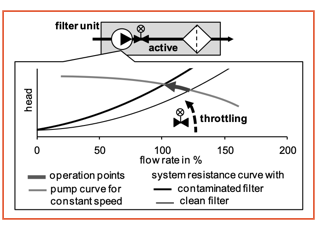
Figure 12. Pump operation with constant
speed
Concept of a Demand Based Operation
The basic strategy is to adjust the cleaning output depending on
the coolant demand in the manufacturing process, with a follow-up monitor. The
procedure is depicted in (Figure 13.) It is made up of two parts: the follow-up
control and the filter resistance determination process.
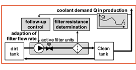
Figure 13. Approach for a demand-based
operation
Follow-up control
The flow rate in the filter system's cleaning loop is
continuously adjusted with a follow-up control dependent on the actual coolant
demand in output. A frequency converter adjusts the throughput of each filter
using speed-controlled filter pumps. As a result, the pump speed and, as a
result, the pump output are continuously adjusted to
the appropriate flow rate and pump pressure (Figure 14).
It should be noted that in filter systems with multiple active
filters, it is also possible to switch off a filter when the coolant demand is
low. However, since the flow keeps the filter cake on the filter components,
the filter can only be removed by backflushing. As a result, the cost of a new
precoating filter aid must be weighed. The key opportunity to achieve an energy
and resource efficient operation is to continuously adapt the flow through each
filter.
Filter Resistance Determination
With the change in filter flow rate, a new filter resistance
determination technique is needed to start the cleaning processes. Filter
cleaning in existing facilities occurs after hitting a given cleaning
intensity. This is possible because there is a clear interaction between the
filter pressure and the filter resistance while the pump speed is constant
(operation point curve in Figure 12). For the same filter resistance, the flow
rate, and thus the flow-dependent filter pressure, varies as the pump speed
changes (operation field in Figure 14). With a lower flow rate, the filter
pressure drops, and the cleaning process isn't activated at the right time. As
a result, the filter pressure can no longer be used as a criterion for filter
cleaning.
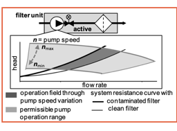
Figure 14. Pump operation with variable
speed control
Modernizations of existing filter
systems are more popular than the construction of new facilities, since
centralized filter systems are part of the service area and have been in use
for more than 20 years. As a result, a retrofit solution based on the proposed
method for existing filter systems is critical. To calculate the payback duration
of a retrofit, the energy savings must be analyzed. So, in the following
section, we'll go over how to model the filter unit, as simulations are needed
to assess the energy-saving potential of various options as well as the control
behavior. After that, the follow-up control's comprehensive architecture is
presented and tested in a simulation scenario.
COMPETITIVE PRODUCTS
Industrial filter systems are
widely used by industries and companies in order to allow for industrial
operations to flow smoothly and be more efficient. There are various types of
filter systems as to which are classified and categorized based on the
industries in which the filter system is applied, the process and method of
filtration, and the material of the filters. In addition, many filter systems
are customized to meet the needs of the user based on the machinery in which
the filter system is being made for. As mentioned, there is an unlimited number
of manufacturers and companies that are known for their filter systems.
However, only four companies that produce filter systems have been taken into
consideration for comparison since they are the closest competitors to the Resy Filter Systems. The competitive products are defined
and listed below. There are more
competitors but only the following would be used for comparison, the rest can
be found in the Appendix of competitors.
|
Examples
of Competitive Products |
|
Shelco Filters- https://shelco.com/products/shelco-industrial-products/ |
|
Tekleen filters for industry and
Irrigation- https://www.tekleen.com |
|
Forsta filters for industrial,
irrigation and municipal applications- https://www.forstafilters.com |
|
Compacto Compact Band filter- https://www.u-techindia.com/product/compact-band-filter/ |
Shelco Filters
Shelco Filters is
one of the many leading industrial filter manufacturers in the United States
since 1973. They design high-quality filters to improve performance at a lower
cost. Shelter Filter Cartiidges are applied in
various high-purity applications such as in petrochemicals, photographic
solutions, pharmaceuticals, cosmetics, and many others. Additionally, Shelco range of industrial filter cartridges are customized
to meet the needs of the customer by the wide range of cartridges such as
stainless steel and carbon block cartridges. In terms of customization, Shelco works with customers to ensure that the right
designed filter cartridge material is used as well as offering the different
design options ranging from duplexing and multiple fittings.
Figure 15: Shelter Filter Cartridges
One of the most common filter
cartridges manufactured by Shelco is the Microsentry SS Series- Stainless Steel Filter Cartridge.
This type of filter cartridge is designed for extreme high temperature
applications greater than 500 degrees Fahrenheit and differential pressures up
to 60 PSID. In this way, the filter cartridge is either made up of 304L or 316L
stainless steel filter media that is used to provide maximum strength. Based on
the design specifications, the filter cartridge can be cylindrical or pressed
filter configurations in order to offer more lasting results as well as allow
for a greater dirt holding capacity.
Tekleen
Filters for Industry and Irrigation
Tekleen water
filters is the industry’s highest quality automatic, self-cleaning water
filters and strainers. These filters are designed for industrial water filters
and irrigation filters. Tekleen Automatic filters has
manufactured over 25,000 filters worldwide and providing filters to over 500
companies. Tekleen water filters are offered for
various applications such HVAC, petrochemical, sea water filtration, power
generation, and even oil production.
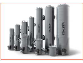
Figure 16: Tekleen
Water Filters
Tekleen water
filters are applied in metal processing. The way these filters' function is by
circulating the water through hot wells, cold wells, and cooling towers to cool
the jacket molds and metal products.
While the operations circulate the water, the dirt particles begin to
enter the system while reducing the heat exchangers function as well as clog
the spray nozzles. This affects the consistency of the metal and the finished
product. However, the finished product may experience many complications such
as metal spotting or break-out. Tekleen works to
self-clean the water filters reducing such complications that may be
experienced while metal processing. These self-cleaning water filters operate
on pressure and are very compact in size making it easier to install.
Forsta Filters
for Industrial, Irrigation and Municipal Applications
Forsta Filters
are automatic self-cleaning water filters that are based on producing less
wastewater while also being more cost effective. These filters are also
designed to function on their own without causing any disruptions to the rest
of the system during the cleaning cycle. In addition, Forsta
filters are low maintenance and provide a high efficiency. These filters are
applied to various industries such as industrial and irrigation. Based on the
industry and application, these filters are customized to specifically meet the
need of the consumer. In this way, these filters range in sizes, orientations,
and degrees of filtrations all in order to accommodate to the application.
Furthermore, Forsta
self-cleaning filters are used to remove particles from the different water
sources. Such particles include but are not limited to pollen, dust, metal
shavings, pipe scale, marine organisms, and fibers. These filters can be
applied to different water sources such as in a reservoir or in wastewater.
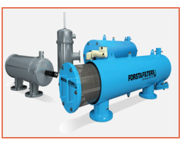
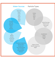
Figure 17: Forsta Filters
Compact Band Filter
Compact Band Filters are
manufactured and designed by U-Tech. These types of filters are utilized in
contaminated coolants that are part of Computerized Numerical Control (CNC)
machines. U-Tech Compact Band Filters are designed to offer better filtration
and efficiency in comparison to other types of filters. The way that these filters function is based on reducing the amount of filter
paper used as well as a decrease in the motor power consumption. That is why
this company states and offers a very high degree of reliability of their
product and guarantees that the Compact Band Filter will reduce the amount of
paper filter and motor power.
The Compact Band Filter has many specified features that allow
it to be distinct and more efficient compared to other filters. This filter is
very compact in the way that it will occupy less space meaning that it only
makes up of one third of conventional paper band filter. As mentioned before,
the design of the filter allows for less consumption of paper allowing for
paper to last much longer. In this way, the paper filters wouldn’t have to be
changed constantly due to the paper lasting much longer than usual filters.
This also saves up on having to buy so many paper filters for the machine. In
addition, the Compact Band Filter can be used to filter coolant and oil with
ferrous and non-ferrous metal and non-metals. Most filters do not function or
are not as efficient when it comes to filtering metal shaving or dust. This
type of filter does in fact ensure that the surface in which is being filter is
left with no residue of any kind leaving a clean and smooth surface. One of the most important features of this
filter is that is made up of microfiber and paper filters that come in various
sizes in order to meet the needs of the consumer.
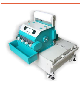
Figure 18: Compact Band Filter
All in all, the competitive products that were taken into
comparison are shown to have similar and distinct qualities when compared to
the Resy Filter System. Most of the competitive
product's function in filtering a system by removing certain particles leaving
a smooth and clean surface. It was noted that out of the four competitive
products, most of them offer customization for the user. What this means is
that users are able to request how they prefer or
would like their product to be. This is mainly based on the
fact that most filters have to be redesigned to fit in certain
machinery. These are similar qualities seen in the Resy
Filter System which why these products have been selected as competitive
products to compare and note that the Resy Filter
System is the better option when compared to these products.
Float level sensor
Water level sensors detect the presence of a liquid in a variety
of ways and use the information to denote its level. For most of us, the
“float” style sensor is the first that comes to mind. A good example is the
float valve in a toilet tank. In the case of the toilet, a float connected to a
lever manually opens a valve to start the flow of water as the tank empties,
then closes it until the appropriate volume is reached for the next flush.
While direct mechanical control is an alternative, in industrial applications,
a small float's movement is commonly used to trigger a switch that sends an
electrical signal to an indicator or a solenoid valve to control liquid flow.
Float switches are the name for these machines.
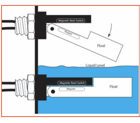
Figure 19: Lever Float Switch
Float switches are simple,
cost-effective, and suitable for a wide variety of applications. They are not
susceptible to the conductivity, temperature, or precise gravity of the liquid
they are detecting, unlike certain other types of liquid level sensors, and can
be constructed from a range of materials to be compliant with most liquids.
They are especially "user friendly" since they are quick to grasp,
troubleshoot, and replace. The most popular instrument for detecting liquid
level is the float valve.
They are not, though, the only
solution to all liquid level sensing problems. Float switches are susceptible
to wear and a range of mechanical failure modes when they have moving
components. When used for plain water, for example, a well-designed float valve
can be dependable. However, if the water contains chemicals that may cause a residue
on the sensor's working components over time, the sensor's durability is called
into question. They have the opportunity to get
“stuck.” This is particularly problematic when a float valve that detects a
high level is constantly wet and dry, causing deposits to accumulate and
solidify, forming a crusty residue. Contamination of particles is also a
problem. Chips and even clumps of magnetic particles may be drawn to the
magnets and block the reed switch's magnetic activation. The magnetic switch is
often replaced by a different kind of switch that detects the angle of the
float by using mercury to bridge contacts in a sealed tube when a certain angle
is reached. However, making reliable communication to the shifting switch
housed in the float, which would, of course, travel up and down, is an issue
with this method. Because of their sensitivity to mechanical injury, it is
recommended that float style level sensors be covered with a small cage or
baffle.
A sealed housing containing an
angle sensitive switch, similar to the mercury switch
mentioned above, is one version of the float switch. The sensor is tethered in
the vessel in this situation so that it floats on its side on the liquid
surface before the critical liquid level is reached. When this occurs, the
tether pulls the sensor to an upright position, which triggers the switch. This
kind of float turn is commonly used in liquid storage tanks.
Microcontroller
A microcontroller (MCU for
microcontroller unit) is a miniature device built on a single MOS integrated
circuit (IC) chip. A microcontroller is a computer that includes one or more
CPUs (processor cores), memory, and programmable input/output peripherals. A
limited amount of RAM, as well as program memory in the form of ferroelectric
RAM, NOR flash, or OTP ROM, is often used on chip. Microcontrollers, in
comparison to the microprocessors used in personal computers and other
general-purpose devices, are designed for embedded applications and comprise of
a variety of distinct chips.
A microcontroller is like, but less
complex than, a device on a chip in modern terms (SoC). A microcontroller may
be one of the components of a SoC, but it is typically paired with specialized
peripherals such as a graphics processing unit (GPU), a Wi-Fi board, or one or
more coprocessors.
Microcontrollers are used in
products and applications that are remotely controlled, such as car engine
control systems, implantable medical devices, remote controls, office
machinery, appliances, power tools, toys, and other embedded systems.
Microcontrollers make it cost-effective to remotely monitor many more machines
and processes by reducing the size and cost of a design that uses a separate
microprocessor, memory, and input/output devices. Mixed signal microcontrollers
are widely used to monitor non-digital electronic devices by combining analog
components. Microcontrollers are a cost-effective and widely used way of
collecting data, detecting, and actuating the physical world as edge devices in the internet of things.
For low power consumption, certain
microcontrollers use four-bit words and run at frequencies as low as 4 kHz
(single-digit milliwatts or microwatts). They can maintain functionality when
waiting for a case, such as a button press or other interrupt; power consumption
while sleeping (CPU clock and most peripherals off) can be as low as nanowatts,
making many of them ideally suited for long-term battery applications. Other
microcontrollers can be used in performance-critical applications, requiring
higher clock speeds and power usage than a digital signal processor (DSP).

Figure 20: Arduino Microcontroller
In addition, Fig.## above which is an Arduino is an
open-source tool that can be used to create electronic projects, which will be
considering using in the SD1 project. Furthermore, Arduino is made up of a
physical programmable circuit board (also known as a microcontroller) and
software, known as an IDE (Integrated Development Environment), that runs on
your device and is used to write and upload computer code to the physical
board.
Vibrational Analysis
Reactive maintenance (repairing a
defect as it occurs), which is gradually being phased out due to its high
costs, and proactive maintenance are two common maintenance techniques in
industry today (based on physical inspections at scheduled intervals of time).
Predictive maintenance is one of the most important fields of study for
industrial motors, as well as aircraft, automotive, and marine vehicles, since
it reduces total running costs significantly. It's founded on the fact that a
mechanical component failure is normally followed by a time of gradual and
crescent regression of action and efficiency. These incipient defects may be
detected, and measures taken before they cause significant problems or harm to
other sections of the equipment if enough on-line tracking is used. Monitoring
of security-relevant components and signals is the state of the art and is
mandated by qualification requirements in the case of mechanical components of
a windmill. The use of a fault detection system in this setting is critical
because it has a number of potential benefits,
including the prevention of premature breakdown, lower maintenance costs by
avoiding the replacement of intact parts during preventive maintenance, remote
diagnosis (which is critical because windmills are typically located in remote
locations), and prognosis and ada. Vibration control
is used in the case of spinning devices, such as the mechanical sections of
windmills (bearings, gearboxes, and so on), and fault detection systems analyze
spectral analysis results, such as FFT, Cep-strum, envelope curve analysis, and
so on, to produce diagnosis and even estimates of the piece's remaining
lifespan. The theory behind this is that noises found in all parts of a
mechanical system will detect almost any flaw. The vibration analysis is based
on the changes that occur in a machine's vibrational behavior when a latent
defect is discovered in one of its components. Predictive maintenance of
windmills is currently performed manually or semi-automatically by trained
professionals, rendering it a high-cost operation. For automated diagnosis and
prognosis, many models have been used, several of which employ Artificial
Intelligence techniques. There are very few articles published in the field of
prognosis. The on-line SBLLM (Sensitivity-Based Linear Learning Method), a
prognostic model based on a supervised feedforward on-line learn-ing algorithm for two-layer feedforward neural networks
based on sensitivity analysis, is presented in this article. The algorithm
provides a compelling combination of speed, accuracy, and simplicity, making it
ideal for real-time prediction.
USER RESEARCH
Filtration technology has advanced
throughout the years. There are various types of filtering processes as well as
the type of filter paper or filter material that is used based on the
specifications of the substances used. In this way, there are questions that
could be asked to potential customers to fully understand their specifications
and expectations when it comes to the filtering technology. For instance, there
are various types of filters that are used for different types of materials
such as those used to filter a substance that contains metal shavings or even
dust. Also, the type of machine that the customer uses is very important since
the filters must be designed to fit in the specified machinery. Most
manufactures do provide filter customizations to meet the needs of the
consumer.
Question that would be
asked to potential customers.
1. What type of
filtering process is your company looking for? Ex. Centrifugation, Paper band
filters, etc. And how big of a scale is the operation you have (Machine wise)?
2. What type of metal
cutting machinery do you have?
3. What type of
appropriate coolant filtering process does your machine need to be in safe
operating conditions?
4. How much space, are
you willing to make/or have for the filtering machine?
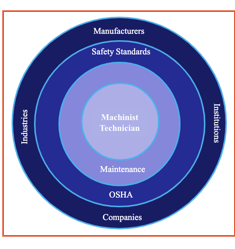
Figure 21: Stakeholder map
It
highly important to understand who the user is and how they may affect other
users. Figure 15 illustrates potential users for filter systems for
industrial machining fluids in a stakeholder map. As it is shown, the user of
the filter system is narrowed down to a machinist technician since they are the
ones who understand and utilize the filtering system machine. Most companies
have a designated person who will utilize the machinery which is known as the
machinist technician. In addition, there are also people who oversee keeping
the machine clean and safe to use which can also be known as maintenance.
Furthermore, the filter system machine is in the hands of the manufacturers.
These manufacturers are responsible in producing the filtering system machine
and distributing it to other companies or customers that have purchased the
product. There will be existing companies as well as new companies that may
want to purchase the product. In addition, there are various industries that
use filtering technology. For this product in particular the industries that
use this product are known. These include but are not limited to the wire and
cable, tooling machine industry, automotive and supplying industry, and the
glass and environmental industry.
Safety
is also something take into consideration. There must be supervision and
inspection of the filtering systems to ensure that they function properly and
are safe to use. There are different organizations such as OSHA that need to
approve that the machinery used is safe to use. The Occupational Safety and
Health Administration should be taken into consideration in the designing of
the product. The product needs to be approved by this organization to ensure
that any material being used will be at no harm to the user. For instance, a
metal used in the product might cause a reaction if a person is in contact with
it leading to a more complicated health issue. If this occurs, the company or
manufacturer may be sued and may be found guilty if this issue occurs amongst
more users. That it is why it highly important to consider the different
materials used in designing of the material and how it may affect the user. In
the case that the safety standards are not met due to any factors such as the
design, the machinery is not allowed to be used or able to be put in the
market. In addition. there are certain standards that are to be followed. While
designing the product, it is highly important to note what the standards are,
and which ones are to be followed. If the product does not comply with the
standards, the product would have to be either redesigned or it wouldn’t be
able to be sold or distributed to the user. There are different handbooks that
include these standards such as the American Society for Testing and Materials.
This is an ‘international standards organization that develops and publishes
voluntary consensus technical standards for a wide range of materials,
products, systems, and services. In addition, suppliers who comply with these
standards are more than likely to offer best quality products to their
customers. In order to ensure that these standards are
being followed, various testing has to be conducted in order for the product to
be ASTM certified.
OSHA
With the Occupational Safety and Health Act of 1970, Congress
created the Occupational Safety and Health Administration (OSHA) to ensure safe
and healthful working conditions for working men and women by setting and
enforcing standards and by providing training, outreach, education and
assistance. OSHA is part of the United States Department of Labor. The
administrator for OSHA is the Assistant Secretary of Labor for Occupational
Safety and Health. OSHA's administrator answers to the Secretary of Labor, who
is a member of the cabinet of the President of the United States. https://www.osha.gov/laws-regs/regulations/standardnumber/1910
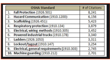
Figure
22: OSHA Top 10 Standards
Six main types of OSHA violations
1.
De
Minimis Violations: A de minimis violation is a technical violation of OSHA
rules that have no direct impact on health or safety. It is the least serious
class of violation, and inspectors do not levy fines or issue OSHA citations
for these violations. Inspectors verbally inform employers about de minimis
violations and list them on the employer's case inspection file. A ladder with
13 inches between rungs rather than 12 inches is an example of a de minimis
violation.
2.
Other-than-Serious
Violations: A violation of OSHA rules that would not usually cause death or
serious injury but that is nevertheless related to job safety or employee
health is considered an other-than-serious violation. According to the United
States Department of Labor, the maximum penalty for each such violation is $13,494.
However, inspectors can choose not to levy a fine, or to reduce the penalty by
as much as 95 percent. Inspectors make decisions about penalties based on
factors such as the size of the business and the cooperativeness of its owner.
Failure to provide copies of safety regulations and failure to post required
documentation in work areas are considered other-than-serious OSHA violations.
3.
Serious
Violations: When an employer knows of or should know of a situation that has a
definite chance of causing serious injury or death, but does not remedy it,
OSHA issues a serious violation. Inspectors must assess OSHA fines of up to
$13,494 for each serious violation, but they can adjust penalties based upon
the seriousness of each particular violation, as well
as the employer's previous history, the size of the business, and the good
faith of the employer. Failure to ensure that employees who carry heavy loads
wear steel-toe boots is an example of a serious violation.
4.
Willful
Violations: The most serious violation category is willful violations, and it
is reserved for intentional violations of OSHA rules or situations that show
disregard for employee health and safety. According to Health Leaders Media,
the minimum penalty for each willful violation is $9,639 and the maximum fine
is $134,937. If an employee is killed, the maximum fine is $10,000, six months
imprisonment, or both. Occupational Health and Safety Magazine shares that more
and more state prosecutors are also pressing criminal charges in these cases.
An example of a serious violation might involve a fatal crushing accident
because the employer did not implement adequate safety procedures for equipment
that had caused prior crushing injuries.
5.
Repeated
Violation: If an employer is cited for a particular violation, and a subsequent
inspection reveals another identical or very similar violation, OSHA inspectors
may cite the employer for a repeated violation. The maximum fine for a repeated
violation is $134,937. However, if the employer contests the original violation
and is awaiting a final OSHA decision, inspectors cannot consider a violation
of the same type to be a repeated violation.
6.
Failure
to Abate Prior Violation: When an employer receives a violation citation, the
citation includes a date by which the employer must remedy the situation. If
the employer does not do so on or before the specified date, it may be liable
for a fine of $13,494 per day from the day after the specified date until it
remedies the condition.
https://work.chron.com/types-osha-violations-10693.html
The objective of the Conceptual Design stage is …
FUNCTIONAL DESIGN
Creating a Functional Reasoning allows us to understand what
the product needs to do, and not necessarily how.
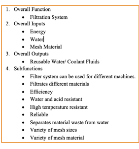

Figure 23: Functional Diagram
MORPHOLOGICAL CHART
The Morphological Chart helps us explore the universe of possible
solutions for each function in an orderly fashion.
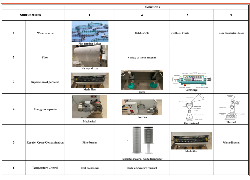
Table 2:
MORPHOLOGICAL CHART
CONCEPT VARIANTS AND SELECTION PROCESS
Combining all possible solutions would generate a factorial number of
concept variants, we had to be selective to find the best ones.
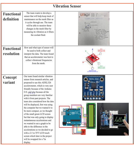
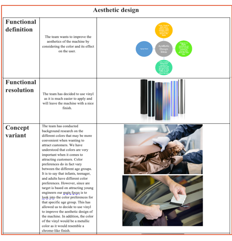
Table 3:
Concept Variants & Selection Process
FINAL CONCEPTS
After the selection process we arrived at the Final Concept.
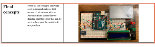
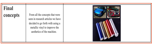
Table 4:
Final Concept for Vibration Sensor &
Aesthetic Design
The objective of the Embodiment Design stage is …
STRATEGIES AND PRIORITIES
Starting from our final concept, we identified the necessary analyses
and engineering work to realize the concept into a product.
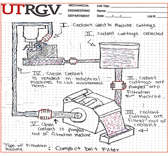
Figure 24: Over all function of the filter machine
TASK 1: CREATE DIAGRAM OF VIBRATION SENSOR
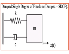
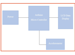
Figure 25: Diagram of Vibration Sensor with Base
excitation model acting as the Filtration Machine
TASK 2: CREATE THE MODEL/PROTOTYPE AND CONFIGURE CODE
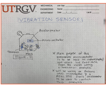
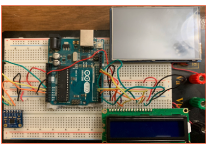
Figure 26a: Rough
Sketch of Vibration Sensor on filtration machine Figure 26b: Model of Vibration Sensor
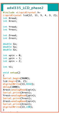
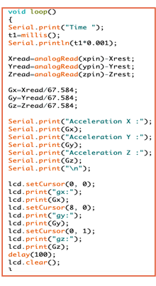
Figure 27: Arduino code for Vibration Sensor
Version 1
TASK 3: CREATE A BLUEPRINT OF THE FILTRATION MACHINE BY TAKING IT
APART
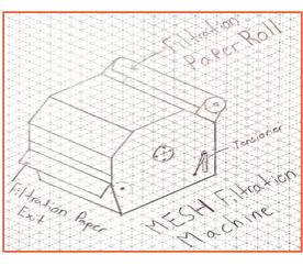
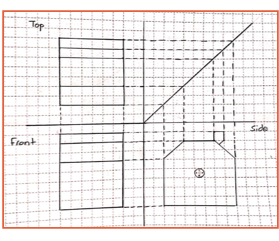
Figure 28(a)
on the left and Figure 28(b) on the right
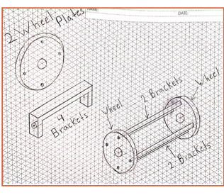
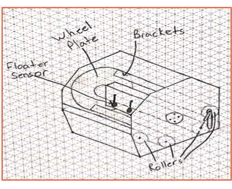
Figure 28(c)
on the left and Figure 28(d) on the right
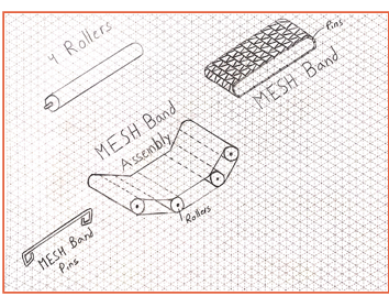
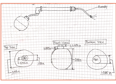
Figure 28(e)
on the left and Figure 28(f) on the right
Figures
28(a, b, c, d, e, f): Student Made Blueprint of the Filtration Machine
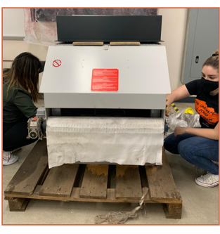
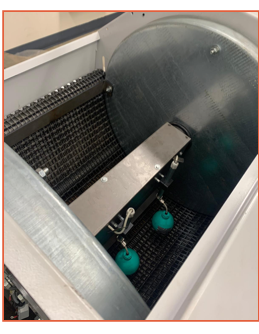
Figures
29: Filtration Machine Model; from where the blueprints were derived from,
Featuring Team members Karla Morales (on the left) and Marissa Sandoval (on the
right)
TASK 4: Conduct research on aesthetic designs
for the filter machine
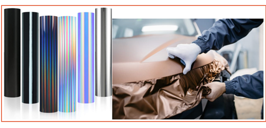
Figures 30:
Vinyl wrap for the Filtration Machine
The team
researched what form of paint/wrap was both efficient with time, and both easy
to apply and remove.
In addition, the team decided on using vinyl
wrap because it had all the necessary characteristics the team needed for the application
in the filtration machine, compared to other methods seen below in the table.
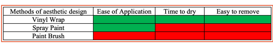
Table 5:
Methods of aesthetic design
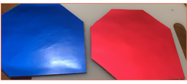
Figures
31: Example of Vinyl wrap colors for the Filtration Machine
TASK 5: Acquire rough measurementS from the
Filtration Machine to create a 3-D prototype model and implement plexiglass
with 7in screen
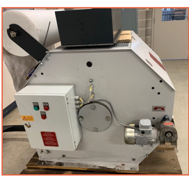
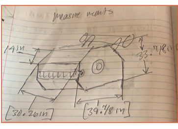
Figures 32:
Actual model next to rough sketch of Filtration Machine with measurements

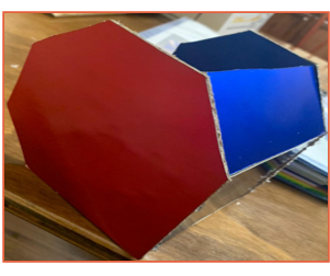
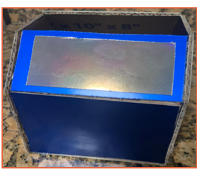
Figures
33: Filtration Machine 3-D model prototype for aesthetic views with
implementation of plexiglass on top
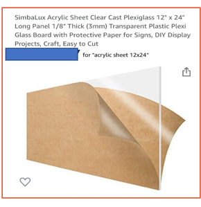
Figures
34: Sample measurements of plexiglass
and 7in screen for Filtration Machine 3-D model prototype
Progression of Embodiment
Design stage FALL 2021
STRATEGIES AND PRIORITIES
FMEA
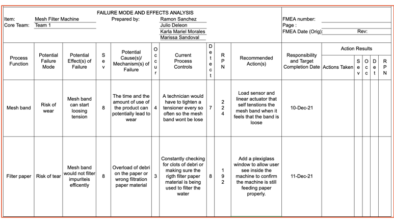
Table 6:
FMEA
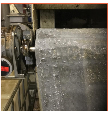
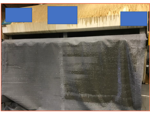
Figure
35: Example of Filtration Machine in Need of Maintenance
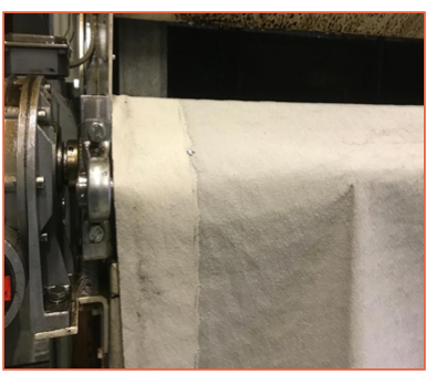
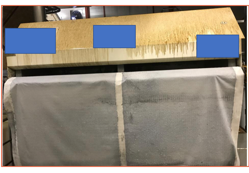
Figure
36: Example of a well maintenance Filtration Machine
QFD
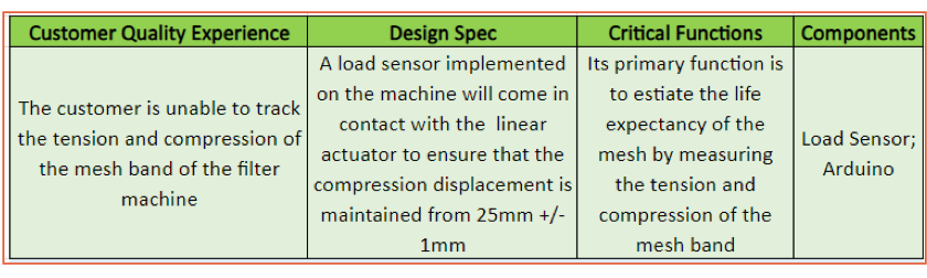
Table 7:
QFD
The objective of the Testing and Validation stage is to see the different
variations of the sensors tested until we got to their Final Version.
PRELIMINARY TESTING V1T1 (VERSION 1 TEST 1): TESTING VIBRATION SENSOR
CODE
This is the testing protocol, the
team started by uploading the code to the microcontroller, until indication light
on the microcontroller said it was ready. After that the team opened a data
plotter on the software to see the reading the sensor is capturing. Then the
team began exciting the accelerometer to see if it picked up the excitations
that were done to it. Since the vibration sensor did pick up and display the
excitations shown below, the decided to test it with a greater excitations
force.
We have added a hyperlink below of a small clip
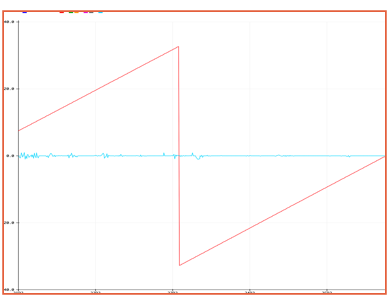
Figure 37:
Test 1, excitation plot
TEST V1T2: TESTING VIBRATION SENSOR WITH A GREATER FORCE
The team decided to test the
vibration sensor with something that would give it a larger amplitude of
excitation. So, the team decided to use the base sound system from one of our
cars which is stronger than most normal cars have. The vibration sensor
succeeded in detecting and plotting these excitations as can be seen below. Now
in future the team plans to test it on the actual machine.
Arduino Vibration Trial with
speakers
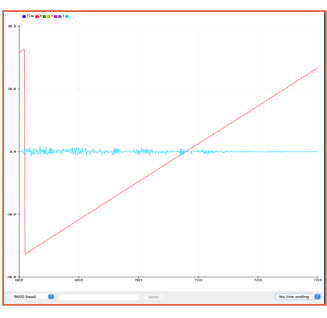
![]()
Figure 38:
Test 2, excitation plot Figure
39: Portion of Vibration
Sensor DATA (X, Y, Z) axis
V2T1 (VERSION 2 TEST
1) VIBATION SENSOR WITH LED LIGHT AND BUZZER
The team
went ahead and took one step further on improving the vibration sensor with the
addition of an LED light and a buzzer to set off an alarm with a flashing light
to signal when the vibration sensor is getting high excitations and let the
user know when the machine requires maintenance.
Development of Vibration Sensor
FINAL VERSION OF VIBRATION
SENSOR TESTING

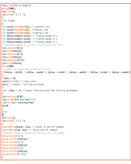
Figure 40:
Final Vibration Sensor Code
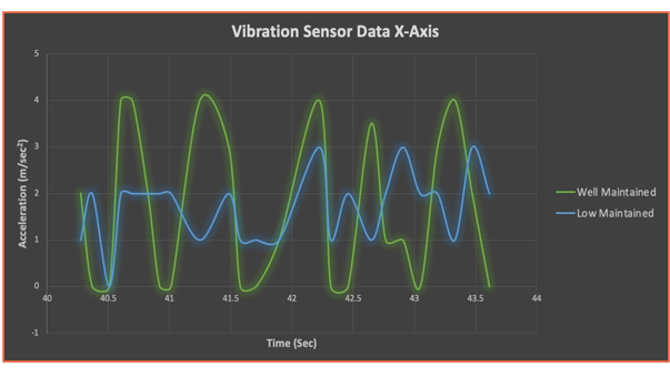
Figure 41:
Vibration Sensor Data Recordings, X-axis
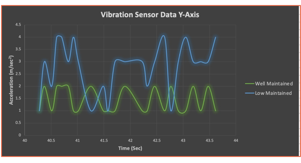
Figure 42:
Vibration Sensor Data Recordings, Y-axis
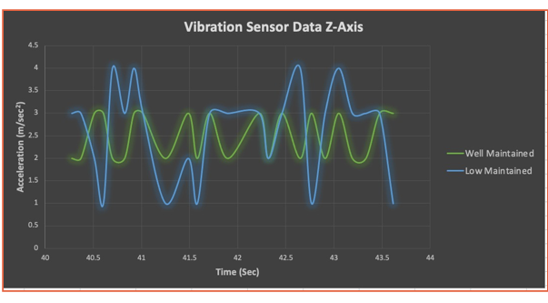
Figure 43:
Vibration Sensor Data Recordings, Z-axis
PRELIMINARY TESTING
V1T1 (VERSION 1 TEST 1): TESTING LOAD CELL SENSOR
The team was able to work with a
100kg load cell sensor and did some research on how it works to be able to
understand its functionality and get data from the machine. The team
successfully developed a code on the Arduino micro controller to help display information
from the load cell sensor to display whenever the load sensor is either in
tension or compression. This data will also help the user know when the MESH
tensioner is either well under tension or in compression.
Development of Load Cell
As one of the methods needed to size the linear actuator, which is
finding working capacity of the MESH band. Our team determined that the best
solution to finding the load capacity was incorporating a linear load cell
between the pneumatic gas spring and base of the machine.
The team is currently working on making the thread cross overs from
6mm threads to 12mm threads in the machine shop. Again, this load cell will
show the user the current working capacity while the machine is operating.
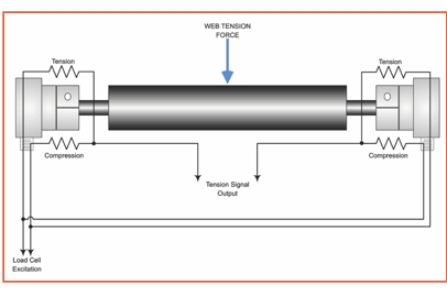
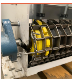
Figure 44a(left):
Horizonal Roller example with web tension cells. Figure 44b(right): Filtration
Machine roller bearing
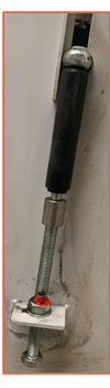
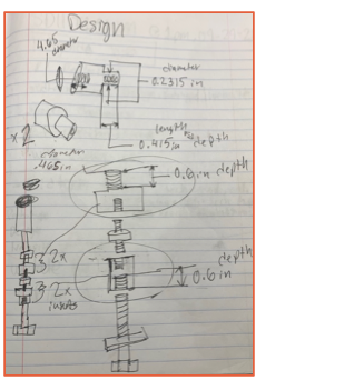
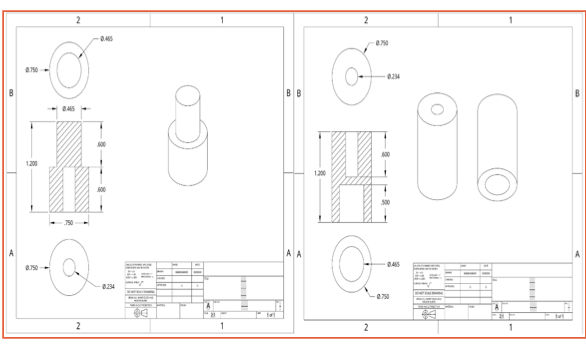
Figure 45a(right): Manual Pneumatic
Tensioner for the Filtration Machine with the incorporation of the load cell
and cross overs
Figures 45b(left): Computer Aid
Design Schematics of Load Cell Cross overs
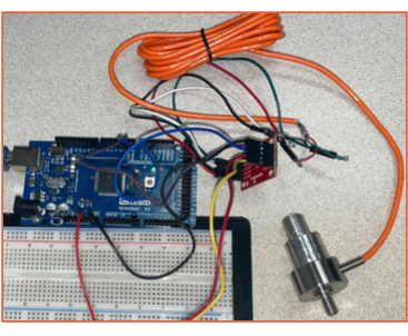

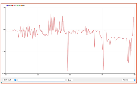
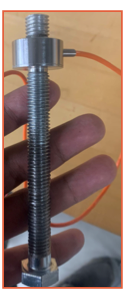
Figure 46:
Load sensor with DATA recordings
Development of
Load cell & Screen
FINAL VERSION OF LOAD CELL TESTING
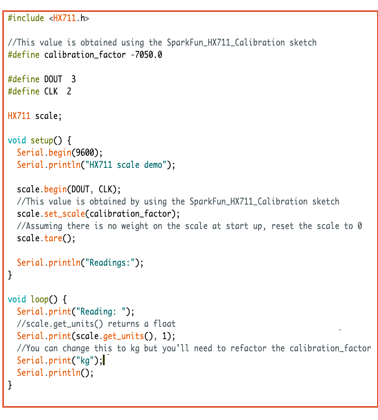
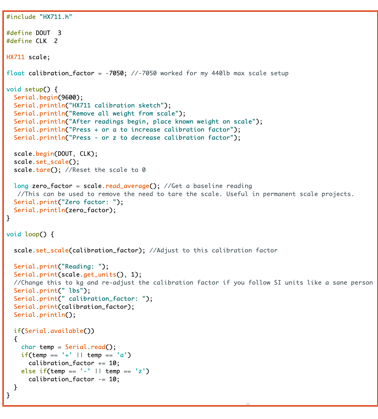
Figure 47:
Final Load Sensor Code
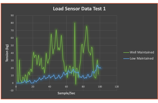
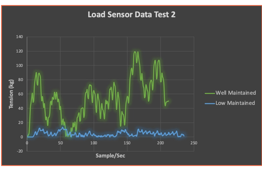
Figure 48:
Load Sensor Data Recordings
PRELIMINARY TESTING V1T1 (VERSION 1 TEST 1): TESTING SLIDING
PLEXIGLASS WINDOW AND LED SCREEN
The team implemented an LED Screen on the filter
machine to allow the user to view the information and data generated from the
vibration and load sensors. The user is also able to adjust the height of the
LED screen by using the housing to make it easier to use. In addition, the
plexiglass is to be placed at the front end of the machine. The user will be
able to slide the plexiglass upwards to facilitate maintenance and be able to
view the filtering process.
Development of Plexiglass Window
Currently the team is working on a solution to mount the plexiglass
sturdy enough to the sliding rails.
The team has currently developed these screen supports to hold the
plexiglass inside it while being able to attach them to the sliding rails.
The sliding rails will be 3D printed
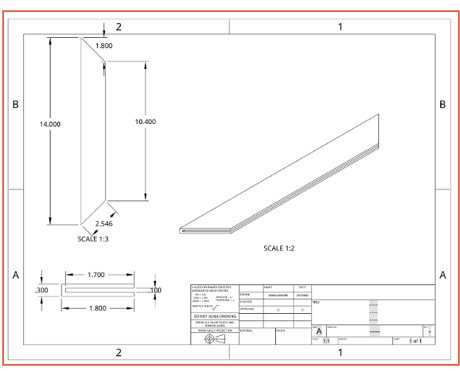
Figures
49: Computer Aid Design Schematics of Screen supports
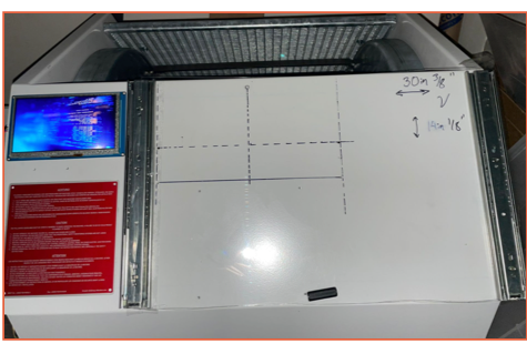

Figures
50: Plexiglass Window Benchmark with LED Screen
CURRENT FILTRATION MACHINE ASTHETIC DESIGN AND MACHINE FUNCTION
Operation of
Filtration Machine
The
team has recently been able to wire and turn on the filtration machine but have
found that we need to reverse the polarization of the motor.
Once
we fix the polarization on the filtration machine, it will allow us to both
find the most efficient placement of the vibration sensor and determine what
frequencies are made when machine needs maintenance.
Aesthetic Design
For our aesthetic design we
will show our final product with our color palette and electrical and
mechanical components incorporated into the machine.
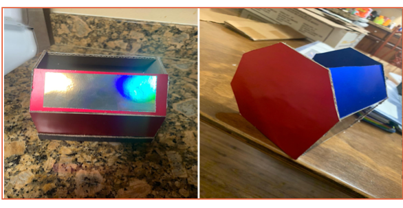
Figure 51:
Load sensor with DATA recordings
Final Aesthetic
Design
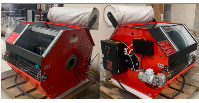
Figure 52:
Load sensor with DATA recordings
This
section is to inform about future work applications on the filtration machine
Linear Actuator
This linear actuator will replace
the current pneumatic gas spring. The replacement of the pneumatic gas spring
will help in preventative maintenance.
Methods which will used to size the linear actuator are the
following
1) Finding working capacity (load/tension) that is being applied
to the MESH belt
2) Travel (Linear Distance, Stroke)
3) Coding (Microcontroller that can handle multiple sensor
inputs)
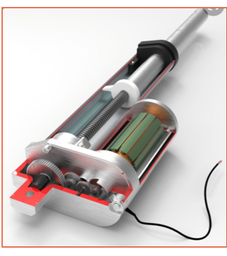
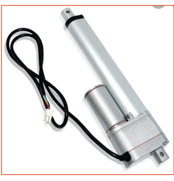
Figure 53:
Linear Actuator
DC MOtor electrical current
sensor
Implementing
this electrical current sensor will allow the technician to see electrical
current loading on the motor while in use.
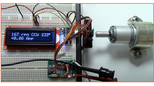
Figure 54:
DC Current Sensor
Microcontroller O.s.
Integrating
this operating system will facilitate communications between all inputs such as
vibration sensor, load cell, screen display, linear actuators
and future input sensors to improve preventative maintenance.
1) Coding
(Microcontroller that can handle multiple sensor inputs)
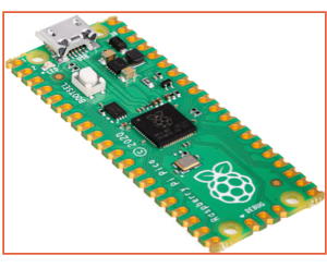
Figure 55:
Raspberry Pi Micro Controller
1.
Forsta Filters. “Automatic Self-Cleaning Water Filters.” Forsta Filters, 5 Aug. 2020, www.forstafilters.com/.
2.
“Shelco
Industrial Products.” Shelco Filters,
shelco.com/products/shelco-industrial-products/.
3.
TEKLEEN. “Self-Cleaning,
Automatic Water Filters for Industrial and Irrigation Water Filtration.”
TEKLEEN Industrial Water Filter and Irrigation Filter - Self-Cleaning Water
Filtration - Automatic Filters Inc., 2021, www.tekleen.com/.
4.
U-Tech. “Compacto Compact Band Filter.” U-TECH, 2021, www.u-techindia.com/product/compact-band-filter/.
5.
Bedard, Risa. “Choosing a
Proper Water Mesh Filter Element.” BoshartU - Free
Plumbing Blogs, Articles and Education,
blog.boshart.com/choosing-a-proper-water-filter-mesh-element.
6.
“Mesh Fabric - History and
Applications: Canvas ETC .” Canvas ETC, 19 Feb. 2019, www.canvasetc.com/mesh-fabric-history-and-applications/.
7. “Top
Industrial Water Filter Companies and Manufacturers in the USA.” Thomasnet® - Product Sourcing and Supplier Discovery
Platform - Find North American Manufacturers, Suppliers and Industrial
Companies, Thomas, www.thomasnet.com/articles/top-suppliers/industrial-water-filter-manufacturers-suppliers/.
8.
Cannon, D., & Cannon,
P. (2019, October 16). Centrifugal separators: Working PRINCIPLE, benefits, and
APPLICATIONS Discussed. Retrieved February 28, 2021, from https://cannonwater.com/blog/centrifugal-separators-working-principle-and-applications/
9.
What is the difference
between vacuum filtration and gravity filtration? (2020, January 18). Retrieved
February 28, 2021, from https://www.labrotovap.com/what-is-the-difference-between-vacuum-filtration-and-gravity-filtration/
10.
HydroGroup®. (n.d.). Sand filter, DEPTH filter, filter GRAVEL, FILTER
SAND, jurassic lime, MARBLE, DOLOMITE, river water
FILTRATION, well water filtration, Filtrate, Flocculant, Water flushing, air
Flushing, MagnoDol, HydroCalcit,
hydrogroup, HYDRO-ELEKTRIK, rwt
gmbh. Retrieved March 01, 2021, from https://www.hydrogroup.biz/areas-of-use/water-treatment/filtration.html
11.
Onur, A., Ng, A., Batchelor, W., & Garnier, G. (2018,
September 12). Multi-Layer filters: Adsorption and Filtration mechanisms for
Improved separation. Retrieved March 01, 2021, from https://www.ncbi.nlm.nih.gov/pmc/articles/PMC6143674/
12.
Saha, U. (2020, October 01). Corrosive or scaling water.
Retrieved March 02, 2021, from https://extension.uga.edu/publications/detail.html?number=B1523&title=Household+Water+Treatment%3A+Mechanical+Filtration+Methods+and+Devices
13.
Rahäuser R., Klemm P., Verl A., Kircher
C. (2013) Increasing the Energy Efficiency in Metal Cutting Manufacturing
through a Demand Based Coolant Filtration. In: Nee A., Song B., Ong SK. (eds)
Re-engineering Manufacturing for Sustainability. Springer, Singapore. https://doi.org/10.1007/978-981-4451-48-2_38
14.
“The History of Water
Filtration.” Pelican Water, 9 Sept. 2014, www.pelicanwater.com/blog/history-water-filtration/.
15.
The principle of vacuum
filtration. (2018, September 06). Retrieved March 20, 2021, from https://www.vacuumfiltrations.com/the-principle-of-vacuum-filtration/
16.
Mein, S. (n.d.). The
importance of Coolants in machining. Retrieved March 20, 2021, from https://www.firetrace.com/fire-protection-blog/importance-of-coolants
17.
Fuchs, J. (2020, February
18). Liquid level sensors - floats. Retrieved March 26, 2021, from https://techblog.ctgclean.com/2020/02/liquid-level-sensors-floats/
18.
Microcontroller. (2021,
February 10). Retrieved March 26, 2021, from https://en.wikipedia.org/wiki/Microcontroller
19.
What is an Arduino? (n.d.).
Retrieved March 26, 2021, from https://learn.sparkfun.com/tutorials/what-is-an-arduino/all
20.
Plantservices.com. (n.d.).
Retrieved March 26, 2021, from https://www.plantservices.com/articles/2006/154/
21.
Martínez-Rego D., Fontenla-Romero O., Pérez-Sánchez B., Alonso-Betanzos A. (2010) Fault Prognosis of Mechanical Components
Using On-Line Learning Neural Networks. In: Diamantaras
K., Duch W., Iliadis L.S.
(eds) Artificial Neural Networks – ICANN 2010. ICANN 2010. Lecture Notes in
Computer Science, vol 6352. Springer, Berlin, Heidelberg. https://doi.org/10.1007/978-3-642-15819-3_9
This
is a summary of important Senior Design files, click on each to open in a
different window.
SDI
REVIEWS
R2
RN
MIDTERM
PRESENTATION
FINAL
PRESENTATION
REPORT
SDII
REVIEWS
R1
R2
RN
MIDTERM
PRESENTATION
FINAL
THIS
WEBSITE