UTRGV / COLLEGE OF ENGINEERING AND COMPUTER SCIENCE / MECHANICAL ENGINEERING DEPARTMENT
TEAM 10: AUV Wave Energy Physical
Simulation

|
SDI
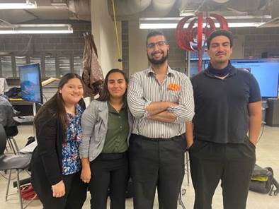
Students (From Left to Right) |
Kathy Garza Cynthia
Contreras Hameem Gorabi Hernán Ramírez |
|
Faculty
Advisor |
Dr. Yingchen
Yang |
|
Course
Instructors |
Dr. Noe Vargas Hernandez Mr. Greg Potter |
Welcome! We are team
#10 “Mech Wolves”, consisting of members Hernan Ramirez, Hameem Gorabi, Cynthia
Contreras, and Kathy Garza, advised by Dr. Yingchen
Yang. Our project (entitled AUV Wave Energy Physical Simulation) tackles the
problem of a lack of available AUV’s with flexible energy generation
capabilities, to which we provide the ‘proof of concept’ viability of wave
energy for AUV’s via a sophisticated physical simulation. We have designed a
device that inexpensively (but physically) replicates the internal motions
involved in wave energy generation via a tank with simulated waves and outputs
an accurate estimation of wave power output that would be received in those
conditions, improving upon the efforts of our predecessor group.
Click on the Welcome
Video below!
This video presents a basic introduction to AUVs and how they
are used. Click here to watch.
AUV’s (Autonomous Underwater Vehicles, sometimes
referred to as UUV’s or Undersea Autonomous Vehicles) require long lasting
energy with minimal top-offs and little to no maintenance for long periods of
time for their underwater missions. Currently this need is provided for via
batteries and occasionally solar, but these are troublesome solutions with a
plethora of necessary tradeoffs and limitations. Wave energy generation
provides power without the need for constant resurfacing or maintenance – and
can do so even from some depth. Brought into a practical design, it may
significantly extend the duration of operation, enabling greater efficacy of the
AUV platform.
A sub-problem of this practical implementation is
the risk-expense of implementing such a system on a prototype – there must be
greater evidence than possibly limited computer simulations that such a system
will output desirable amounts of energy. A physical simulation using a simple
mass-spring-damper setup instead of a full wave energy one can provide a close
simulation of energy output while taking potentially unseen variables into
account, providing a clearer picture of what an actual system will be capable
of, and doing some of the design heavy lifting.
To better understand the AUV market and the ways
in which a wave energy product can contribute to it, we have conducted detailed
research on the topic. Listed here are notable snippets of this research which
helped drive our designs, provided useful general information, or were just
plain interesting.
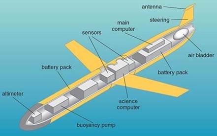
-
AUV’s have a torpedo-like shape for drag reduction, so internal components need
to cater to this form factor
-
AUV’s are used for research, commercial, military, and exploration purposes
(among others)
-
AUV’s are capable of deep-sea operation, able to operate at up to 6000 meters
below surface level. Some models can go even deeper!
-
AUV battery lifespans can vary from hours to months depending on the battery
source used, but cost scales more than linearly with duration. Two times the
duration means more than two times the price for batteries – a problem energy
generation doesn’t have.

AUV’s are a fast-growing market, expecting up to
a 20.8 percent increase in market size from 2020 to 2027 (Bizwit Research &
Consulting LLP, 2020). They find use in research, exploration, military, salvage,
rescue, ocean floor monitoring and more. Several noteworthy organizations and
institutions including but not limited to those listed as users on our stakeholder
map (shown below) make extensive use of AUV’s, most of which benefit from
improved operational duration – which is what we’re working on with wave
energy.
PROPOSED SOLUTION
“We propose several key improvements on
the design of a novel energy capture mechanism that transforms the natural
ocean wave motion energy into electrical energy for autonomous underwater
vehicle (AUV) extended operations and seek to implement them on physical
simulation platform[nv2] .”
After coming to
understand the problem at some level of depth, we have begun the design process
and come to a proposed solution to work through. To get a brief understanding
of the improvements we aim to implement, click here.
‘Classic’ AUV Design:
Last-Gen Physical Simulation Wave Generation Design (Springs,
though absent, were featured):
Physical Simulation of Wave Generation Design:
Present Physical Simulator Design (3D CAD Model):
[To see this project in progress, check out the ‘Prototype
Early and Often Section’!]
Once our solution
concept became clearly defined, we began applying our engineering knowledge to
‘bring it to life’ so to speak. Listed below are a few of the most significant
challenges in no particular order, accompanied by
descriptions of how we have addressed them.
1. Overall size/weight constraints for
buoyancy
This
is a balancing act that required attention during nearly every step of the
design process, including when facing other challenges. Still, we were able to
settle on a ~4’’ diameter and 25” length (more than a 50% increase from the
last group’s dimensions) in order to provide more space for air and make a more
efficient system with a larger mass while remaining neutrally buoyant.
2. Minimal damper length/size, maximum
damper stroke length
Unfortunately,
no dampers on the market that meet our specifications exist – so we took it
into our own hands and fabricated some ourselves. We’re using lightweight
aluminum partially hollowed out, with emphasis on a larger internal air chamber
and a small air output port hole, to damp sufficiently but keep motion going.
The input/output port will be small air holes, to be drilled larger as needed.
3. Smooth damped oscillation of mass for
ideal energy generation
While the damper has some
bearing on how smoothly the mass will move, it’s not the only notable factor. A
strong rod material, proper alignment, symmetrical mass, minimized deformation
of the system when in motion, surface compatibility, lubrication and more all
contribute to the smoothness of the motion. Once we took care of our damping
concerns this was the next priority.
4. Strong, ocean-safe materials for general
housing (some must be clear to examine the system at work)
There was some initial
conjecture about making the housing clear PVC. It’s cheap, see through, and
seems to do OK with water – the only problem was that it would definitely
deform under some serious motion and that would mess up our precious alignment.
After running through a few more options, our advisor recommended
Polycarbonate. Clear and salt-water compatible like clear PVC, but also strong
and durable – everything we needed it to be. It’s our definitive housing of
choice.
5. Accurate, compact, and non-intrusive
sensor setup
We went for the most
non-intrusive sensor possible – an external one. With a high framerate camera and
moderately high resolution we can observe the oscillating mass behavior with enough
detail to analyze it.
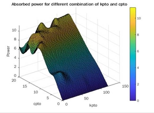
Our design specifications were
influenced by the predecessor product and existing analysis of its optimal
power output based off a modeling of the ‘system’ (provided by Mahmoudul Maheen, a graduate
student who works on AUV research with Dr. Yang, and us by extension). The
theoretical power output of the predecessor system is quite small due to the lower
scale of the previous prototype. The design decision to increase scale was to
simplify fabrication and increase system efficiency, but also to make it
simpler to bring to working order, which the previous group had a lot of
trouble with. The size of the mass (the analogue to the magnet in the magnetic
coil generator we’re simulating) corresponds strongly to the simulated output –
the larger the mass, the larger the output. More importantly, the greater the portion
of the overall assembly goes to the mass, the more efficient the system is –
the ‘mass budgeting’ required for buoyancy has less relative cost as certain
components (like the outer tube or guiding rod) do not need to be scaled up as
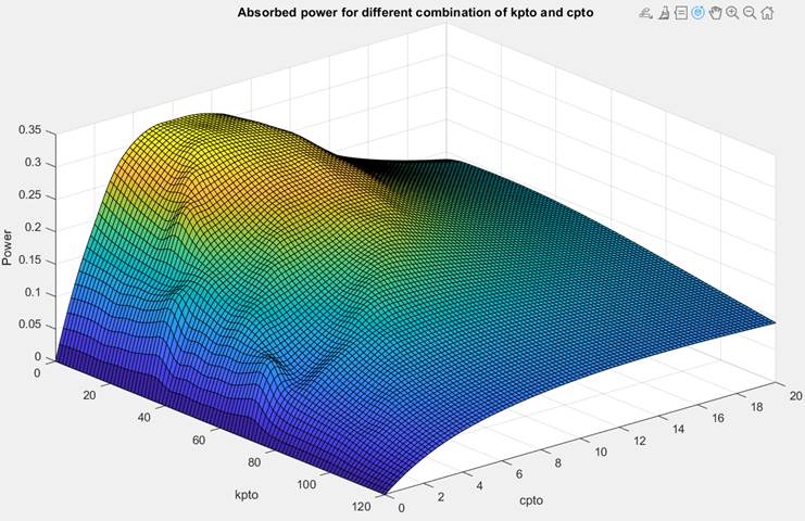
much to maintain efficacy. On the left is calculated watts power generated
based on prospective kpto (system spring constant,
N/m) and cpto (system damping constant, Ns/m) for the
predecessor system, and on the right is the same modeled calculation but
updated to reflect the changes made in our system. For reference, the prior
maximum theoretical wattage was less than a single watt and the new maximum
theoretical wattage is a little over 11 watts.
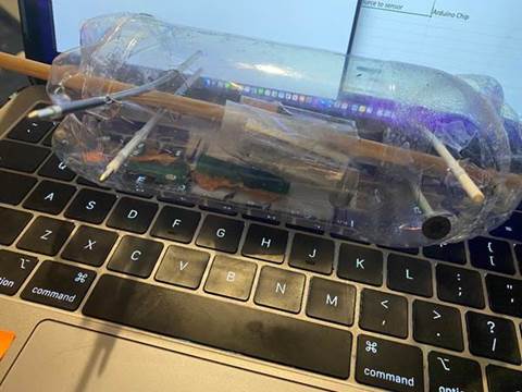
Physical prototyping using available
materials can quickly bring a design to life without needing all the labor and
detail-work for a full functioning product. Using our prototypes, we were able
to identify flaws and other attributes we simply missed while constructing them
mentally. A few of these rapid ‘junkyard’ prototypes are shown below, with
explanatory subtitles.
In the above prototype, an
oscillating battery would be used instead of some portion of the mass. The idea
is that it can power some of the internal systems until wave power kicks in
without serving as dead weight. Observing this rapid prototype made us realize
that the wiring would be a mess for a moving battery meant to power a sensor or
some aux systems – and would detract from energy generation in a non-simulation
design.
This
prototype is much closer to what we want to build. The mass is aligned with the
rod, the springs configured where the spring-dampers would be, and the housing
roughly similar to what we have in mind. It does lack endcaps – an issue we
will need to consider.
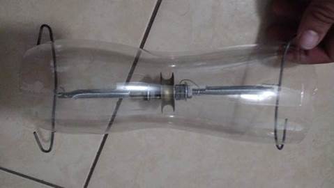
Here is
an advanced ‘junk yard’ prototype – it closely resembles what we wish to build.
In place of air-sealing damping chambers, there are small springs in the inner
tubes. A block of wood with an attached wooden rod represents our mass and rod
configuration, and the tube itself is close to our expected form factor. The
cut-away section is for demonstration purposes – our final build will be
watertight.
PROTOTYPE DEVELOPMENT
----
The details below describe the work and progress of the final prototype----
Throughout
the course of three summer months, we gathered the materials we ordered or
needed and had blueprints for the manufacturing of each part to begin the manufacturing
process. The following is the work done in the summer of 2022 and the following
months:
Damper Base:
·
Aluminum 6061 4” disc
·
2 damper bases
·
Lathe and CNC for manufacturing
The damper bases are used for the placing and the alignment
of the rod through the prototype.
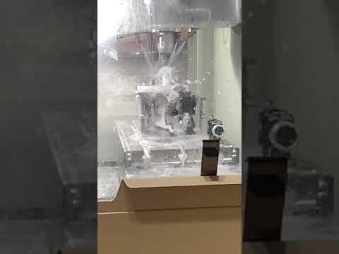
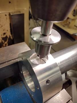
Manufacturing:
·
Easily the most difficult to manufacture of all
parts – greatest complexity and trickiest features.
·
Ultimately produced by making the basic shape on
the lathe, CNC milling the curved slots, and using a manual mill to implement
the back and side holes.
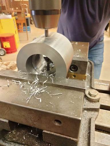
·
Port for air drilled using a micro-chuck and fine
drill to start with, gradually going up in diameter.
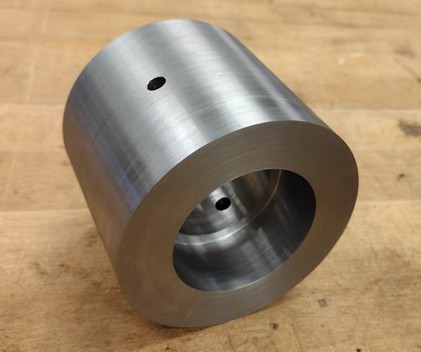
Damper Tube:
·
Aluminum 6061 round tube
·
2 damper tubes
·
Lathe machine
The damper tube is used to connect to the damper bases where
it holds the rod into place.
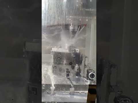
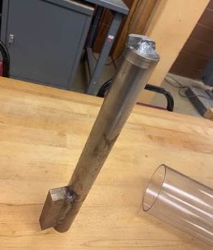
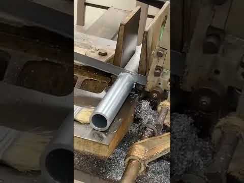
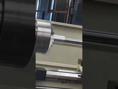
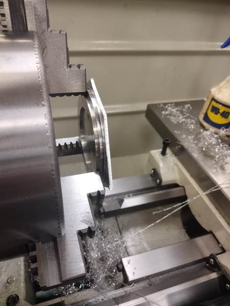
Manufacturing:
·
Made from a piece of aluminum tube stock – none
came at the specified thickness we required, so we had to hollow it out more
ourselves, which was tricky because of the limited reach of the lathe tooling
and the necessity of good alignment/straightness.
·
The hollowing out was done with tooling welded to
a steel cylinder and block for extra reach and produced on the lathe (shown
below next to the manufacturing clips). The notches at the end were done with a
manual mill.
Polycarbonate Tube:
·
Polycarbonate tube
·
1 polycarbonate tube
·
Saw, sander, and drill
The polycarbonate tube holds the majority of our materials
together due to the high impact resistance.
Manufacturing:
·
The tube ends required facing after being cut to
size to maintain alignment for initial design.
·
The spring pin holes also required precise
placement and alignment.
·
Extra care had to be taken during both these
processes to not warp or bend the piece, to maintain straightness and
concentricity to a small tolerance.
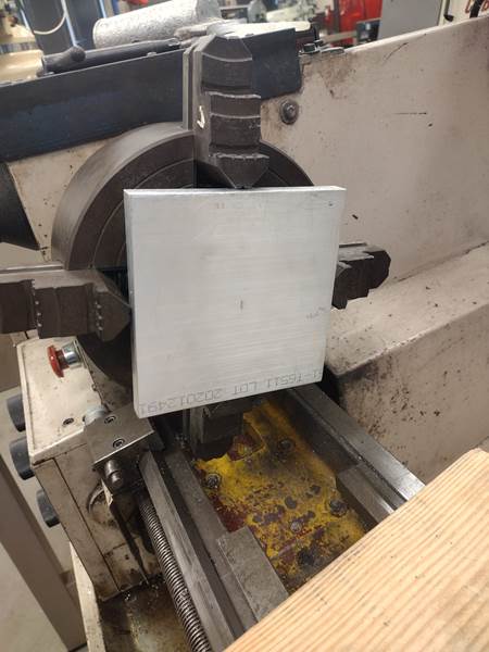
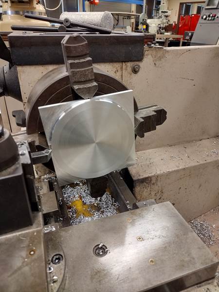
Mass:
·
Low carbon steel disc
·
1 mass
·
Lathe and Mill machine
Mass is the most important part for our prototype’s purpose.
It can show us how much energy can be simulated with the motion due to the
waves.
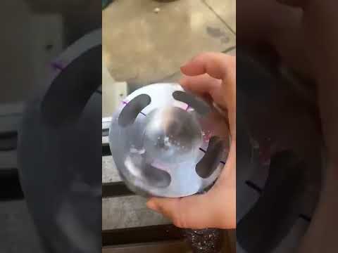
Manufacturing:
·
The mass of this piece plays a central role, so
avoiding excess material removal was a priority, more so than with other parts.
·
Manufactured mostly with a lathe, with the mill
being used to install the holes.
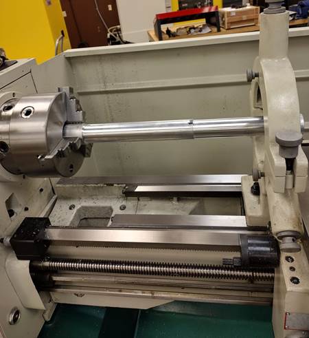
Rod:
·
Aluminum 6061
·
1 Rod tube
·
Lathe machine and drill
The rod is used to hold the mass
and it moves freely through the damper tubes.
Manufacturing:
·
Mostly produced with a lathe, the hole being
drilled with a mill.
·
Required additional support on the lathe due to its
long length (pictured below partway through production).

Caps:
·
Aluminum 6061 sheet
·
2 end caps
·
Mill machine and drill
The caps are designed to be used to enclose the polycarbonate
tube from water entering the tube by pressing a rubber O-ring into place.
Manufacturing:
·
Round edges produced on lathe; holes drilled on
mill.
·
Had to be produced carefully because of very
small grip area.
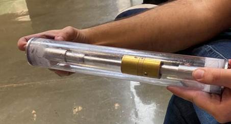
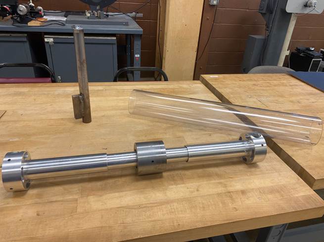
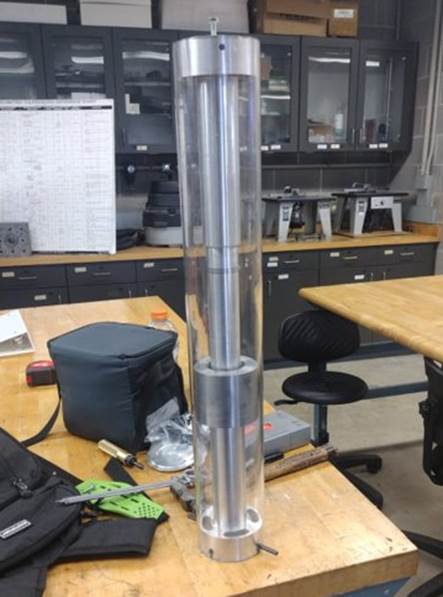
The Advanced (Close to Final) Prototype:
·
Assembly of parts described above, with some
changes as required
·
Design concerns at the point of this assembly:
waterproofing and smooth motion
·
Recent addition of springs for the latter concern
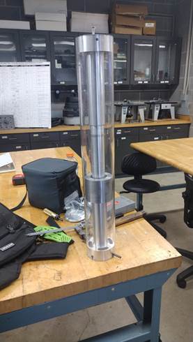
Quite close to our final research product, has been
troubleshooted until operational since then.
Revisions:
Since this is an Engineering project, things didn’t go fully
to plan. The pressure the endcaps exert on the O-rings to seal the assembly
work – but only insofar as they prevent water from entering, as they mess up
alignment. We were somewhat prepared for this potential outcome – the endcaps
were relatively small and not used to anchor the assembly to the polycarbonate
tube, designed with the knowledge in mind that they may not work as they should
in theory.
·
A few options had already been ruled out earlier
in the design process, when considering waterproofing and the need for
disassembly/reassembly.
·
A low-pressure seal using ‘waterproof’ sealant
tape was an option – no practical way to model it, so we tested it out:
·
Good, but in this quantity and arranged over a
tube it wouldn’t last. Follow up idea from a technical consultation: produce an
ideal area to seal off the assembly with an ‘over-the-top’ rather than inner
endcap. Weight restrictions and the nature of its larger size meant it couldn’t
be metal.
·
The need for a custom shape and size meant 3D
Printing was a good fit for fabrication. Our instructor, Mr. Gregory Potter,
introduced us to the skills and material selection necessary.
·
After some fiddling with the size and
specifications, an endcap set was produced!
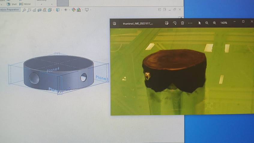
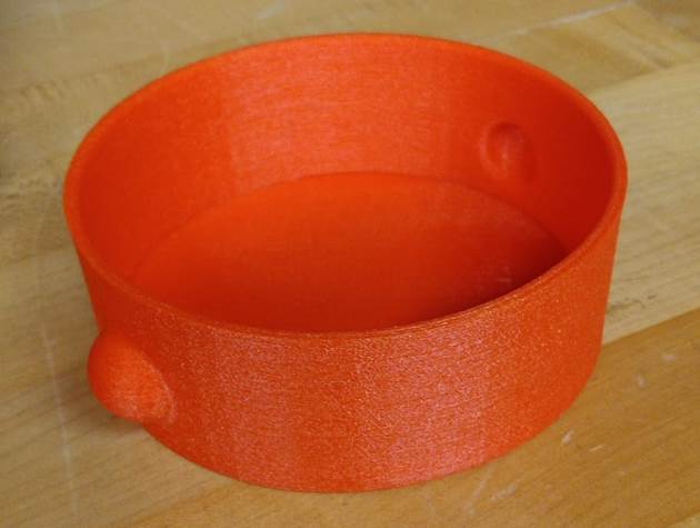
·
And it didn’t work. There was nothing wrong with
the design or the printer – a reprint with a higher quality brand of the same
material, TPU, produced an endcap that did work, bringing us to our final
prototype with which we are conducting tests with:
·
Additionally, springs were installed to
facilitate smooth motion – they do not alter how we fundamentally analyze
damping of motion as an electrical generation analogue because they add no
energy, they merely redistribute it in the service of better motion.
Our
final output is a research-oriented product and shaped up looking a little
different to the CAD design shown in ‘Proposed Solution’. Put under a wave or
wave-like motion, it now smoothly oscillate its inner mass – damping some of
the motion in the process. This damping is a physical simulation of a
conversion to electrical energy – the amount of motion that gets converted.
It’ll allow us to calibrate and troubleshoot the system without the huge
spending or lengthy fabrication that the same process would require on a full
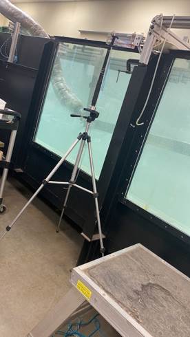
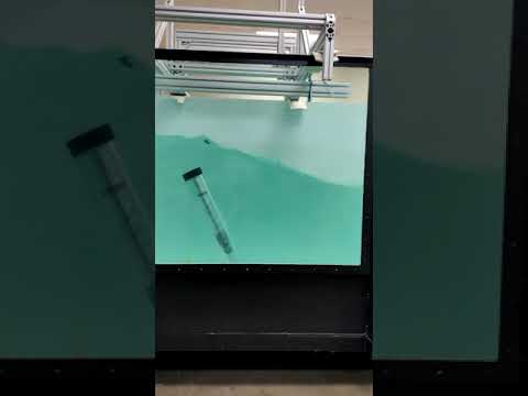
generation prototype (or series of prototypes). We’ve begun the testing of our
prototype using a rotor-motor and a large water tank with simulated ocean wave
motion (the ‘wave tank’ for brevity), shown below.
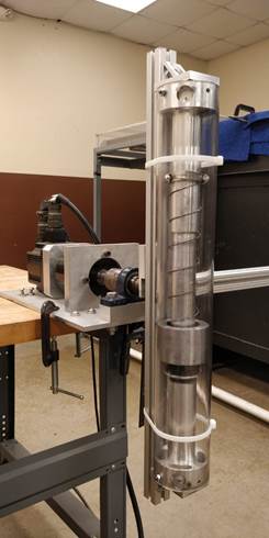
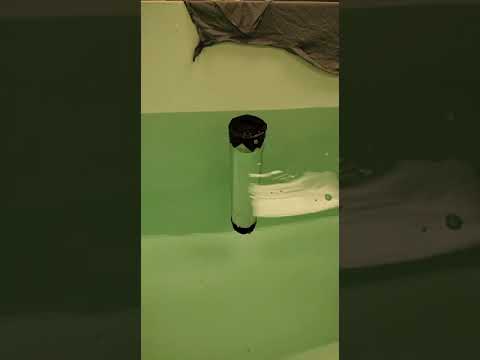
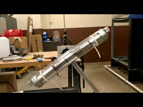
Here
the rotor motor shows the full range of mass movement – our goal is to get as
much of this range in practice with the wave tank as we can.
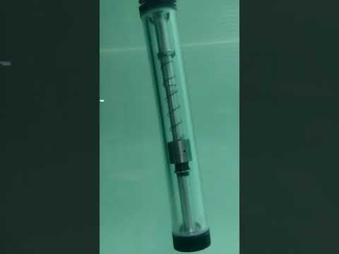
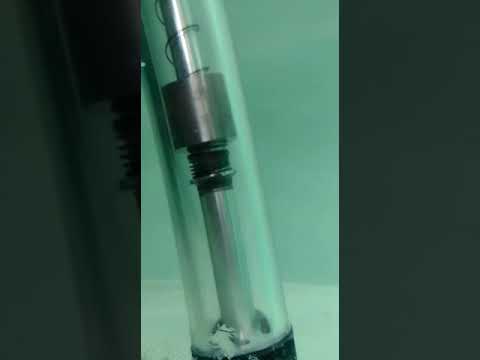
We’ve
begun testing a range of controlled conditions using the wave tank, so we can
see how wave frequency and port size affect the prototype (and the relations
with our theoretical analyses). Here are some clips of the final prototype in
motion during tests for 1/8” at 0.5 Hz (left) and 5/32” at 0.7 Hz (right).
These are just two of them – there are many, many more we’ll be using for
post-testing analysis.
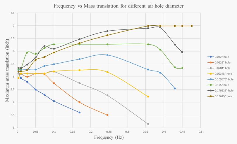
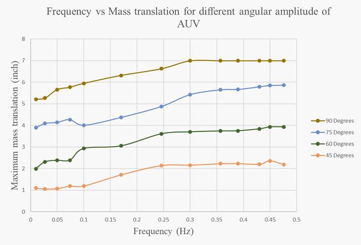
The
testing we’ve accomplished so far has been focused on the variables of frequency,
maximum mass translation, amplitude, and hole diameter. A few relationships
between variables emerge, like the maximum translation of the mass dropping off
for most hole size configurations after a point of frequency (seemingly
specific to the diameter of the hole) or differences in angular amplitude
affecting the magnitude of mass translation strongly but the way it relates to
frequency weakly. Translation is an important value for calculating how
effectively and how efficiently the simulated capture of energy is going.
Future work involves
using calibration data to further refine physical simulators and
simulations, cumulating in the production of a wave electric
generation system using coils and a magnetic unit, with large swaths of the
system already calibrated and troubleshooted. Among further calibration
concerns include size calibration - evaluating several scale
variations for their viability in the AUV's that support their
form factor, and if proportionate scale variation affects system properties in
notable ways. Additional concerns
include the study of system function under variable
conditions, chiefly concerned with weather or ocean conditions
that affect wave motion properties. In the more immediate future, more testing
needs to be done with the present prototype so that a better baseline dataset
can be established.
IN CONCLUSION
Our Senior Design project has contributed to the advance of ocean wave energy generation in a compact AUV platform, using our predecessor’s designs to improve our own and giving our work forward for our successor’s project, and AUV wave generation research beyond. We have successfully manufactured and tested a functional research prototype and begun the collection of data by the time of project completion. Senior Design I&II and the crucial lessons learned by our group in design ideation, refinement, and fabrication, and more has served us well in our project endeavors and will do so far beyond it.
REFERENCES
Bizwit Research & Consulting LLP, 2022. Global
Autonomous Underwater Vehicle (AUV) Market Size study with COVID-19 Impact, by
Type (Shallow AUVs (up to 100 meters), Medium AUVs (up to 1,000 meters) and
Large AUVs (more than 1,000 meters)), by Technology (Collision Avoidance,
Communication, Navigation, Propulsion and Imaging), by Payload Type (Camera,
Sensor, Synthetic Aperture Sonars, Echo Sounders, Acoustic Doppler Current
Profilers and Others), by Application (Military & Defense, Oil & Gas,
Environmental Protection & Monitoring, Oceanography, Archeology &
Exploration and Search & Salvage Operations), by Shape (Torpedo, Laminar
Flow Body, Streamlined Rectangular Style and Multi-hull Vehicle) and Regional
Forecasts 2020-2027. [online] Available at:
<https://www.marketstudyreport.com/reports/global-autonomous-underwater-vehicle-auv-market-size-research?utm_source=marketwatch.com&utm_medium=SHR&utm_campaign=marketwatch>
[Accessed 22 February 2022].
Team 10 Mech Wolves,
2022. SD1 Project Proposal
We went through a meticulous design
process to arrive at the end results shown on this page. The information in
this page is a summary intended for the general public. To learn about the
project details, contact Dr. Noe Vargas Hernandez at noe.vargas@utrgv.edu
Our
team, the Mech Wolves, owe in large part the successes of this project to:
Dr. Yang, who gave us guidance and
advice.
Mahmodul Maheen for
significant theory, fabrication, and testing guidance and contribution.
Dr. Vargas, for general guidance.
Mr. Potter, for rigorous constructive
feedback and significant guidance on 3D printing.
Mr. Hector Arteaga for practical
specifics and fabrication guidance and advice.
Mr. Antonio Suarez for fabrication guidance
and advice.
The
Hi-Bay and Machine Shop employees and students, who freely assisted us whenever
we asked or simply looked like we needed help.