 UTRGV / COLLEGE OF ENGINEERING AND COMPUTER
SCIENCE / MECHANICAL ENGINEERING DEPARTMENT
UTRGV / COLLEGE OF ENGINEERING AND COMPUTER
SCIENCE / MECHANICAL ENGINEERING DEPARTMENT
TEAM 8:
Wave Powered Autonomous
Underwater Vehicle
(Design
Process Page)

|
SDI Students (L-R) |
· Javier Benavides · Bryant Chiu ·
Fernando Guerrero Rivera ·
Gerardo Salinas |
|
Faculty Advisor(s) |
· Dr. Yingchen Yang |
|
Course Instructors |
· Dr. Noe Vargas Hernandez · Mr. Greg Potter |
|
College of Business and
Entrepreneurship Collaboration |
· Dr. Reto Felix
(Instructor) · Annet Del Toro Villarreal · Hugo Gutierrez · AnaKaren Rios · Omar Rodriguez Perez · Mayra Varela |
Back to
the PROJECT MAIN PAGE.
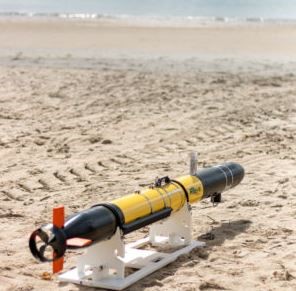
During Senior Design we followed a
design process to make the Autonomous Underwater Vehicle be able to travel from
point A to point B underwater using MRE (Marine Renewable Energy).
Problem ID
Problem Formulation
Conceptual Design
Embodiment Design
Testing and Validation
The
objective of the Problem ID stage is to help the user identify what the problem
to be solved is, as well as to brainstorm in order to
figure out a way to solve the problem. The team thought not only about what our
own take in order to solve the problem would be, but
also the competitors that are already on the field and how can we differentiate
our product from the competitors.
POG’S
There are many diverse types of
renewable energies such as solar, thermal, wind, and hydropower energy. The
team determined the best way to solve the problems is to utilize wave energy
(hydropower). Essentially, wave energy is produced via the frictional force
generated when the wind hits the surface of the ocean. As
it stands right now there is two methods of utilizing wave energy. One method
is to utilize the energy supplied by the wave and converting it into electrical
to power a battery housed in the system. The other method is for the propelling
force to be direct from the wave via mechanical systems.
VOA
The following VOA chart(s) compare our proposed
product to the closest(s) competitors:
|
AUV (Autonomous Underwater Vehicle) |
Team 8
G.B.J.F ENGINEERING |
|
|
|
|
|
|
|
|
ATTRIBUTES |
LOW |
MED |
HIGH |
|
Cost Efficiency |
|
|
• |
|
Energy Efficiency |
|
|
• |
|
Communication System |
• |
|
|
|
Depth Rated |
|
• |
|
|
Minimal Impact on the Marine Ecosystem |
|
|
• |
|
COMPETITOR 1: SeaRaptor |
TELEDYNE MARINE |
|
|
|
|
|
|
|
|
ATTRIBUTES |
LOW |
MED |
HIGH |
|
Cost Efficiency |
• |
|
|
|
Energy Efficiency |
|
• |
|
|
Communication System |
|
|
• |
|
Depth Rated |
|
|
• |
|
Minimal Impact on
the Marine Ecosystem |
|
• |
|
|
COMPETITOR 2: Comet-300 |
RTSYS |
|
|
|
|
|
|
|
|
ATTRIBUTES |
LOW |
MED |
HIGH |
|
Cost efficiency |
• |
|
|
|
Energy Efficiency |
|
• |
|
|
Communication System |
|
|
• |
|
Depth Rated |
|
|
• |
|
Minimal Impact on the Marine Ecosystem |
|
• |
|
As
you can see from the tables above, we determined our product will shine in cost
efficiency and energy efficiency. Since our AUV will not need to be retracted
to recharge resources will be saved there. Also, missions will be safer for those
in charge of the AUV.
FINAL PROBLEM
STATEMENT
While ocean robots
have proven to be particularly useful in many applications they are
limited by a crucial factor. Battery powered autonomous underwater
vehicles are limited by the capacity of its battery. Due to this problem,
they are limited to short term functions. As stated in the article a
battery powered AUV is limited to “hours to days” and “tens to hundreds of
kilometers. “[3] While the longevity and
physical capacity is our focal point, it is not the
only issue that would be resolved. A successful wave
powered AUV would open a world of exploration
for hydrographic surveyors, pipeline inspectors, and ocean observers.
The main objective of the problem formulation stage is to establish a clear problem. In order to do so we conducted extensive research on the following topics.
BACKGROUND RESEARCH
POWER SOURCES
AUV power
sources can be broken down into three categories nuclear, combustion, and
electrochemical. We
will be focusing on electrochemical.
There are four different categories of
electrochemical power sources.
· Pressure compensated batteries (batteries discharged at ambient
pressure)
· Batteries discharged at atmospheric pressure
· Fuel Cells
· Seawater batteries
Note: Outgassing is the formation of gases during charging. Outgassing
complicates charging and discharging. If a battery outgasses then the gases
must be removed from the cells to prevent an explosive environment.
|
Chemistry |
Energy Density (Whr/kg) |
Life (Cycles) |
|
|
Alkaline |
140 |
1 |
Outgassing during high temp |
|
Lead Acid |
31.5 |
100 |
Outgassing |
|
Silver Zinc |
100 |
30 |
Outgassing |
|
Ni Cad |
33 |
100 |
Flat discharge curve |
|
Ni MH |
60 |
500 |
No outgassing |
|
Li Ion |
144 |
500 |
Limited by depth |
|
Li Polymer |
193 |
500 |
No outgassing |
As it can be observed in the table above lithium
polymer cells possess great energy density, low weight density, and long life. Furthermore, they
do not outgas making recharging simpler.
Materials
Materials suitable for underwater navigation
need to have high strength-density ratio. Material such as metals have a
tendency of corroding underwater. Chemicals present in sea water that led to
corrosion are nitrates, acids, sodium, and other chlorides. The main question is
what can be done to minimize these factors to minimize the problem of corrosion
in sea-going vessels. The research was conducted by G.B.J.F. Engineering.
AUV Sensors
AUV's built-in sensors provide an
abundance of valuable information, such as depth. AUV's can be equipped with
still or video cameras, sonar, magnetometers, fluorometers and dissolved oxygen
sensors. AUV's can communicate with each other via radio waves, but radio waves
are not capable of navigating through water. AUV's utilize the last known GPS
information and makes use of a built-in inertial navigation system. The
function of the inertial navigation system is to document the vehicle's
rotation, acceleration, and velocity. This function is also known as "dead
reckoning" The profundity of the vehicle can be estimated using a sensor
capable of measuring pressure. AUV's may have various underwater
implementations. Commercial applications include observation of environment for
oil and gas industry and searching for wrecks. Military applications include
reconnaissance and anti-submarine warfare. It would also be innovative in the
research department. A long-range H-ADCP is incorporated in the AUV's payload
to measure wave flow tempo profiles. The profiles are used by the vehicle to
institute path rectification to improve the vehicle's robustness. The mission
is replicated when the vehicle arrives at the deduced wave field or when a
necessity to renovate the deducing wave field is found. The wave fields created
by the varying vortices supplies a rough estimate of the spatial wave
administration, which is based on the turbulent field effects. The number,
centers, and intensities of the vortices closest to the AUVs are determined
from the H- ADCP profile. The AUV then can map the trajectory with the least
amount of navigation time in the newly constructed sector. AUV's must be able to operate in ocean circumstances
distinguished by complicated ocean circumstances. Unpredictability of the ocean
can vigorously unsettle safety conditions and evolution of AUV missions.
Forecasting and learning ocean currents is an especially important obligation
to enlarge the AUV's safety when encountering unpredictability.
Communication
Communication underneath the water is based
on acoustic waves. It can take up to 2 seconds to reach back and forth in a
1.5-kilometer distance. Communication can be affected by scattering, refraction and absorption through the water. Hollow waters
and reef formation is where coordinated robotics can be most difficult to have
communication in the ocean. It is also difficult to communicate with robots in
hollow waters and reefs, which can be difficult for coordinated robotics. The
communication will be completed at a very low bit rate. This is due to physical
limitations which include delay and attenuation. Dolphins have given experts
inspiration to carry information based on location and communication. Engineers
came up with a tool named the "ultra-short baseline" (USBL) tool to
help with the communication. The USBL tool is based on chirps, which will be
used to communicate with the ship. The information will be sent in bytes and
kilobits, in the form of a frequency signal. The idea comes from dolphins' use
of singing and calls.
USBL is a type
of acoustic reading that can tell you positioning. It does this by being an
extension of a computer modem. Sound is transported from here towards the AUV
which then replies with a new pulse. This rebound signal can be read by a
computer located on the ship.
Coordinated
Robotics is a project that is of great importance to pave the way for future
underwater communication research. The company is working on such solutions to
fasten delivery time and create bigger chances for opportunity.
COMPETITIVE PRODUCTS
Due to the high
volume of competitors we narrowed down our
research to 7 AUVs. Each of these AUVs represent a subsection sharing
similar characteristics. Below is more
information pertaining to each of the 7 AUVs.
1.
TELEDYNE MARINE
Because this is a modern technology, there
are few competitors. One of the main competitors is the company Teledyne
Marine, which is one of the leading companies in the development of AUVs. Its
main AUV is the SeaRaptor, which can travel from
3,000 to 6,000 meters deep.
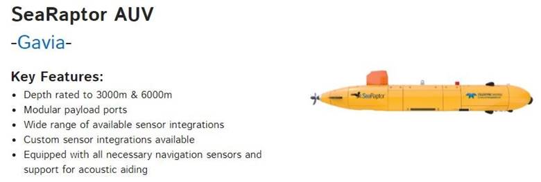
URL: http://www.teledynemarine.com/searaptor-auv?ProductLineID=15
|
COMPETITOR
1: SeaRaptor |
TELEDYNE MARINE |
|
|
|
|
|
|
|
|
ATTRIBUTES |
LOW |
MED |
HIGH |
|
Cost Efficiency |
• |
|
|
|
Energy Efficiency |
|
• |
|
|
Communication System |
|
|
• |
|
Depth Rated |
|
|
• |
|
Minimal Impact on the Marine
Ecosystem |
|
• |
|
2.
RTSYS
RTSYS is a company based in France. This company
is specialized in underwater acoustics and robotics. RTSYS offers two varieties
of AUVs which serve similar purposes. The Comet-300 AUV offers advanced
navigation as well as a communication system capable of displaying navigation
and position data in real time.
URL: https://rtsys.eu/comet-300-auv
|
COMPETITOR 2: Comet-300 |
RTSYS |
|
|
|
|
|
|
|
|
ATTRIBUTES |
LOW |
MED |
HIGH |
|
Cost Efficiency |
|
• |
|
|
Energy Efficiency |
|
• |
|
|
Communication System |
|
• |
|
|
Depth Rated |
|
• |
|
|
Minimal Impact on the Marine
Ecosystem |
|
• |
|
3.
Monterey Bay Aquarium Research
Institute
MBARI is an advanced center for ocean research
and technology development located in Moss Landing, California. The development
of their AUV, has the purpose of investigating important marine areas, which
due to the lack of technology, have not been able to be investigated
properly.
URL: https://www.mbari.org/at-sea/vehicles/autonomous-underwater-vehicles/
|
COMPETITOR 3: DORADO |
MBARI |
|
|
|
|
|
|
|
|
ATTRIBUTES |
LOW |
MED |
HIGH |
|
Cost Efficiency |
• |
|
|
|
Energy Efficiency |
|
|
• |
|
Communication System |
|
|
• |
|
Depth Rated |
|
|
• |
|
Minimal Impact on the Marine Ecosystem |
• |
|
|
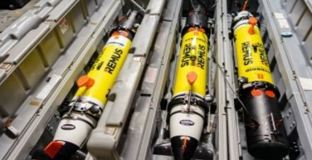
4.
Tiburon Subsea
Tiburon Subsea supplies renting and
lease facilities for global underwater technology. To provide vendors of
maritime facilities and businesses with the newest technology and assistance.
Their focus is on autonomous underwater vehicles (AUV) and a broad affiliate
network. Their engineering staff operates, trains
and provides services to a multinational AUV fleet whose systems are fitted
with payload packages including integrated benthos sonar systems, multi-beam,
sonar side scans, magnetometers and sensors for bathymetry.
|
COMPETITOR 4: REMUS |
Tiburon Subsea |
|
|
|
|
|
|
|
|
ATTRIBUTES |
LOW |
MED |
HIGH |
|
Cost Efficiency |
|
• |
|
|
Energy Efficiency |
|
• |
|
|
Communication System |
|
• |
|
|
Depth Rated |
• |
|
|
|
Minimal Impact on the Marine
Ecosystem |
|
|
• |
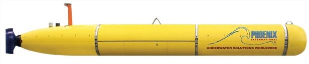
5.
Phoenix International
Artemis, the
Autonomous Underwater Vehicle of Phoenix International, is an
compact deep-water search/survey system that functions with two field-swappable
payloads. For effective single-pass data collection, the acoustic payload is a
multi-beam echo sounder, a dual frequency side scan sonar, and a sub-bottom
profiler that can be worked simultaneously. The optical payload is a high resolution payload that is (1936 x 1456
pixels) To build photomosaics of seafloor objects, the b&w camera was used. The geophysical payload is a
3-axis magnetometer, a 3-meter dipole electrical field (self-potential sensor),
a CTD and a bathymetric and backscatter running multibeam echo sounder. Doppler
Velocity Log, Ring Laser Gyro, and depth sensor combined with an Ultrashort
Baseline onboard inertial navigation system (USBL) The system produces
extremely precise, repeatable and accurate vehicle
navigation and positioning.
|
COMPETITOR 5: Artemis |
Pheonix International |
|
|
|
|
|
|
|
|
ATTRIBUTES |
LOW |
MED |
HIGH |
|
Cost Efficiency |
|
• |
|
|
Energy Efficiency |
|
|
• |
|
Communication System |
|
|
• |
|
Depth Rated |
|
• |
|
|
Minimal Impact on the Marine
Ecosystem |
|
• |
|
6.
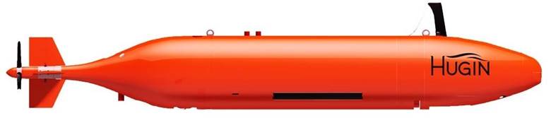
KONGSBERG
The ultimate in autonomous remote
subsea survey capability is offered by KONGSBERG who provides the HUGIN
Autonomous Underwater Vehicles - AUV / marine robot. The great maneuverability
and high precision of stabilization characterize these free-swimming autonomous
underwater vehicles. The ideal choices for these AUVs are hydrodynamic shape,
precise instruments and outstanding battery
capacity.
|
COMPETITOR 6: HUGIN |
KONGSBERG |
|
|
|
|
|
|
|
|
ATTRIBUTES |
LOW |
MED |
HIGH |
|
Cost Efficiency |
|
• |
|
|
Energy Efficiency |
|
• |
|
|
Communication System |
|
• |
|
|
Depth Rated |
|
• |
|
|
Minimal Impact on the Marine Ecosystem |
|
• |
|
USER RESEARCH
·
AUV ́s AND THEIR MISSIONS AND
APPLICATIONS
An AUV can carry out a wide variety of activities. Analysis,
industrial applications and surveillance applications
are three major types. All these activities require human risk because they
require risk-taking.
AUV is an important instrument for collecting samples for
research studies. It is difficult for humans to do so largely because of the
high hydrostatic pressure. AUV's are also used in detection, search
and rescue, launch and recovery systems in the defense industries. AUVs are
used in the marine sciences, marine chemistry, marine geology, interstitial
water, marine biogeochemistry and underwater drilling
platforms.
·
AUV used in commercial applications
AUVs can also help in prevention and correction of maintenance
as well as inspection of activities. Underwater net opticfiber
has been created for underwater communications. AUVs can be used to monitor and
control underwater activities in the ocean. They can also be used for
underwater telecommunications in real-time.
Certain research created for
oil and telecommunication companies have been included in
literature. An AUV “equipped with an auto tracker, sensors such as
lateral search sonar, a geo positioner, shape recognizer based on
neural networks, so via the simulation of algorithms of each module,
incorporate into the physical part of the AUV.” [22]
Hazardous underwater
environments can be of great issue for not only access for humans, but also for
the AUVs; AUVs can be trapped during missions. When exploring through
solutions, a “C++ language can be implemented by estimating the error
between the position of the AUV and element.” [22] Such examples include
in pipelines or cable.
·
AUV used in surveillance applications
Subaqueous conditions are unforeseeable because of frequent alterations
of weather circumstances. There exists a very high chance that a military
operation will not succeed.
The independence of Autonomous underwater vehicles are characterized by two factors: “amount of
hours of operation necessary without occupying support and
the capability to make crucial commitments to undergo
a successful mission.” [22] Obviously,
the autonomy is a crucial feature in missions of surveillance, currently
research has been executed. New architecture of controls are
suggested to reach levels with characteristics of autonomy.
The autonomy of AUV ́s are represented by two aspects: number of hours of work
without needing any assistance and the ability to made decisions to carry out a
mission. The autonomy is an important feature in surveillance
missions, “research has been carried out where new control architecture
was proposed to meet the terms with aspects of autonomy referring to the
decision making in the missions in which the AUV ́s initially lacks
information.” [22]
DESIGN
SPECIFICATIONS
The design of the AUV will be made
taking in consideration the three distinct sections in
which the team has divided the vehicle. The
three sections that we have divided the vehicle are:
·
The Front Payload Bay
·
Power Take-Off Unit
·
Rear Payload Bay
The reason why the team
has decided to make this in the design of the AUV is because it helps the
assembly process. The assembly process is and must be of extremely
high importance since this could lead to imperfections throughout the
model, and when talking about an underwater vehicle there is plenty
of room for little mistakes to happen. Therefore, the team
in ordinance with Dr. Yingchen Yang
decided that creating this scheme will help avoid these tentative
issues towards the near future.
·
The Front Payload Bay
Regarding the Front
Payload Bay, the professor and advisor Dr. Yingchen Yang
mentioned something particularly interesting that the team
did not appreciate until it was commented with us, this is the fact that
when the AUV will be in different water circumstances you will always want it
to go down, even when we are not there to handle it ourselves. This made
us think that since the front part of the AUV, similarly to any other type of
underwater vehicle such as submarines, the first part or the part that leads
when the vehicle will sink. [23]
Therefore,
the form of the AUV must have a certain weight that will help the
overall body of the vehicle to sink even when there are storming conditions
that might bring it up towards the surface. [23]
·
Power Take-Off Unit
In the Power Take – Off Unit
section, the team will have to take in consideration for the design of
the AUV that the main component present which will be the stator
set, the battery pack, the magnets, as well as the
translator assembly. The stator set will be the non-moving
essential piece of the electric generator (also known as the motor) which
will help in the energy flow process as the stator lets the
energy navigate to the mechanical components of the AUV which will lead to
its movement. [23]
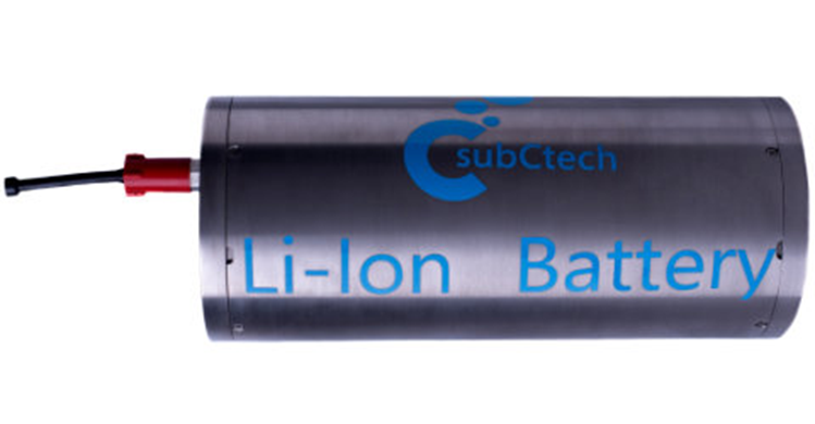
The battery pack will require to apply
some necessary specifications, as that this will be the only method for
which the AUV will be able to communicate and supply service due to no possible
way of receiving any source of charge in the middle of the ocean. An
important piece of advice that the team has acquired thanks to
research throughout distinct AUV models is that Lithium-Ion
batteries, seem to be some of the most reliable ways for us to store the energy
the AUV will be able to generate. [23]
An
important aspect that we must cover to have a good battery in the AUV is the
capacity of energy that it will be able to store. The capacity of the battery
will depend on factors such as the mass of body, its components, and the
surface of the AUV. The distance it can travel its directly proportional to the
weight of it. The AUV's battery capacity will also depend on its mass and the
temperature.
Therefore, the team will try to find a
suitable battery capacity once the overall weight of the AUV
is known. Inside the Fron Payload Bay
section, there will be the utilization of magnets to hold
in place the battery pack and avoid the movement of the batteries, this will
also help to hold up the section as a whole
and provide enough magnetism for the battery pack
installed. The AUV also counts with translators which will help with
the task of calculate the instantaneous position of the
vehicle in relation to the waves of the ocean, this will help
the AUV to approach the waves to gain kinetic energy out of it.[23]
An important piece of advice given to the team by
Dr. Yingchen Yang, is that the AUV must have a certain weight to it,
this will have to be acknowledged by the team when picking the different
polymer materials, and the amounts of it that will be used in the production of
the vehicle. The reason for the AUV needing to have a certain weight
is that the team must make the vehicle as
heavy as possible because this will be what will help it sink again if by any
reason is thrown off by a wave, by an animal that could uplift it to the
surface of the ocean, or by any outside effect. [23]
However, the team should
also make sure that it is not too heavy because if its weight happens to
surpass a certain mark then it will sink to the bottom of the ocean, therefore
a limit must be set regarding the weight of it. For us to
properly give the AUV the weight we are looking for the team was advised
to take in consideration the weight of the Battery pack as well
as the included magnets, since these will be the
ones responsible of the power generation for the vehicle, and
this in addition with the translator assembly will be the effective for the
team to manage the mass. [23]
·
Rear Payload Bay
Rear Payload Bay is composed of the propeller,
the ballast tanks, and the control and instrument sensor. The propeller will be
the necessary for the AUV to move from one place to another. If the propellers is affected or destroyed by some incident in the ocean then
the vehicle will find itself stuck with little or no room to repair it.
In order to avoid these
issues, the propeller must be made from a durable material that
can last for extended periods of time and will not damage. The damage
the material might suffer depends on distinct aspects such
as the temperatures under which it will be found, as well as the pressure
that it will be under and the type of water that the AUV will navigate as the
different pH these bodies of water might feature.[23]
Another
important part of the Rear Payload Bay will be the ballast tanks, which will be
filled with water for navigational purposes. When the AUV is positioned in the
surface level of the body of water, the ballast tanks will fill up
with air. This means that the whole density of the vehicle will be
significantly lower in comparison to the water, and it displaces. The AUV will
have to dive back into the water, and during this process, a vent will be
released and make the water in the surrounding of the AUV to dash inside.
Nonetheless, we must know
that this is not the only function the ballast tanks have, since they
can be filled up with not only water but with the amount desired of a
gas in a compress form, this with the purpose of submerge and go back to the surface
as the user desires. In this case the AUV will be able to back to the
surface, through the use of compressed air
which will be found in
the ballast tanks though an air flask and
this will propagate the water to get out by being pushed with a high
pressure and at a high speed which will make it easy for the AUV to
go back to the surface again.[23]
The team has also intended in
integrating a control and instrument sensor which will work in
regard to different formations found across the path of the AUV. These
sensors will be able to tell when possible damage
sources appear along the way and help the vehicle avoid them. The ocean is
difficult to predict in the sense that we are not able to know the different
settings it will encounter, as well as the different animals that are under the
sea and levels of water.
Ø Housing of
AUV
The housing of the AUV is one of the most
important parts of the vehicle, this will protect and keep together the
mechanism and since this will be under distinct circumstances, we
need to produce a material that can be utilized in the different
settings. [23] An advice that Dr. Yingchen Yang
gave to the team is to prioritize the housing of the AUV to remain in a
void environment, this is especially necessary because having any sort of leak
throughout the body of the AUV can cause the vehicle to sink and therefore
stop working and would be a complete failure. [23]
The housing of the AUV is intended of being
constructed out of a non-magnetic material because if it is intended
to be used for military purposes by the government, the team must use a
material that will not result affected is an enemy tries to steal the AUV
device by using magnetic devices. Also, because of the battery and the
magnets used to hold the battery together we must use non-magnetic materials in order to not affect the environment of the
power bank. [23]
The material necessary to build a proper AUV
housing must be made out of composite materials and/or
metal alloys. The ideal material for the housing of the AUV, would be out a
composite of titanium alloy. However, due to monetary constraints the team
needs to figure out a more affordable and easier to obtain material. The team
was able to notice the properties of this composite materials due to prior
investigations made by IEEE Xplore.
These composite materials are also extremely
helpful for the AUV because of their light weight this feature, as mentioned
above we need to have an essential weight to the AUV and having these
lightweight materials to our advantage will help us have more chances
of distributing the weight of the other components as we
desire. [23]
Another benefit of using this aluminum and
titanium composite material alloy is that the AUV
will feature a higher corrosion resistance across the
housing, it is imperative that the corrosion resistance of the vehicle must be exceedingly
high specially because it can go under unknown circumstances
when it is used for exploration or for missions by the NAVY. This
circumstances also require the freedom of changing the shape design
of the vehicle depending on the mission or the reasoning behind
it, and the aluminum alloy as well as titanium alloy give the
chance to the user of changing the shape of the AUV as
they desired, and it would be easier for the team to create a more
specific shape depending on the requirements. [23]
The
objective of the Conceptual Design stage is to determine the equipment
necessary for the assembly of the AUV. This while identifying what requirements
does the AUV has to fulfill. After the analysis of the essential parts of the
AUV, the team will identify how to integrate them in the system.
FUNCTIONAL DESIGN
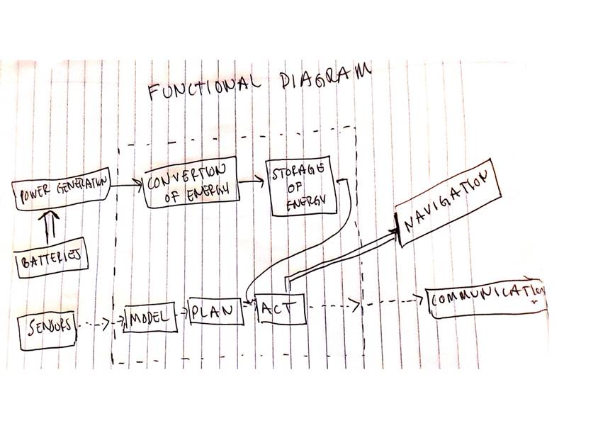
MORPHOLOGICAL
CHART
|
Sub Functions |
Solution 1 |
Solution 2 |
Solution 3 |
Solution 4 |
Solution 5 |
|
Power Generation |
Use Solar Energy By adding solar
panels |
Use Wind energy
by adding a small wind turbine |
Integrating an
alternator system |
Using waves to
oscillate a spring system attached to a battery to charge |
Use an internal
combustion engine using biofuel |
|
Accumulation of
Power |
Implement lithium
batteries, known to be one of the longest lasting batteries in the market. |
Implement
alkaline batteries in high volume to withstand long distances. |
Utilize a backup
battery in case of emergency. |
Lead Battery (Car Battery) |
Vehicle 416mm Low-Voltage battery |
|
Communication |
Detection of
large objects via use of a detection radar. |
Implementation of
a GPS system so operator always knows location |
Implementation of
heat sensors, in order to perceive any unrecognized
activity underwater. |
Use of night
vision camera, in order to arrange missions during
dark/deeper environments. |
Typical Wifi band (2.4GHz) |
|
Being able to be
submersed underwater |
Use steel to
build AUV |
Use polymers to
build AUV |
Use more
sophisticated materials such as carbon fiber |
Use Aluminum
Alloys |
Use Titanium |
|
Military and
Border Security Applications |
Applying a small
security camera with low capacity for recording. |
Placing a GPS
system, to find location of illegal activities. |
Recognition of
heat patterns, to locate recent activity. |
Small device to
dismantle mines for military protection. |
Develop a UAV
capable of storing an anti-submarine explosive device. |
|
Data Collection |
Applying a small
tank for collection of water. |
A small imaging
system to capture images of the surroundings. |
Sensor of pH
balance in the different bodies of water, for research purposes. |
Integrate valves
on the surface, that can be controlled by the user to accumulate the samples
required. |
Collecting sand
samples |
|
Hydrodynamics |
Shape 1 |
Shape 2 |
Shape 3 |
Shape 4 |
|
|
Sub Functions |
Solution 6 |
Solution 7 |
Solution 8 |
Solution 9 |
Solution 10 |
|
Power Generation |
Use a
conventional high-performance electric motor. |
Implement a new design
in the AUV with the purpose of using ocean currents and generating electrical
energy. |
Use nuclear
energy as the main source to power the AUV. |
Implement an
engine which runs on natural gas |
Implementation of
the principles of osmotic energy to generate electricity through salt water |
|
Accumulation of
Power |
Vehicle 416mm High-Voltage battery |
Vehicle 310mm Low-Voltage battery |
Vehicle 310mm High-Voltage battery |
Vehicle 260mm Low-Voltage battery |
Vehicle 260mm High-Voltage battery |
|
Communication |
WLAN and Radio Communication |
Acoustic modems |
Frequency dependant attenuation |
Satellite
communications |
Aerostat hotspot |
|
Being able to be
submersed underwater. |
Use an
anticorrosive coating on the material used in the manufacture of the AUV
hull. |
Implementation of
anticorrosive paint on the hull and different components of the AUV exposed
to salt water |
Protection of
materials exposed to saltwater using anti-corrosion cathodic protection. |
Acrylonitrile Butadiene Styrene |
Ni-base Corrosion Resistant Alloy
|
|
Military and
Border Security Applications |
Used for wreck
inspection |
Install a defense
system capable of firing torpedoes against boats or mines. |
Implementation of
AUVs to check damaged ships after naval battles. |
Radar capable of
capturing electromagnetic waves generated by other ships. |
Capable to deploy
supplies to the army during war. |
|
Data Collection |
Equip the AUV
with a small drill capable of drilling stone at the bottom of the sea. |
Install a
mechanical claw to obtain aquatic plant samples. |
Equip AUV with a
net designed to catch small species of fish. |
Install a
compartment to collect fossils. |
Install a system
able to collect sounds and frequencies coming from the bottom of the ocean. |
CONCEPT VARIANTS
AND SELECTION PROCESS
The team had
to generate different concepts through CAD Software (Solidworks,
NX) and after having multiple variations of the AUV design, the team proceeded
to identify which AUVs designs would result to be more useful in the practice,
as well as with the recommendations of the advisor.
|
|
CV1 |
CV2 |
CV3 |
CV4 |
CV5 |
CV6 |
CV7 |
|
SF1 |
Wave energy with spring system 9,9 |
Alternator system7,10 |
Wave energy with spring system 9,9 |
Alternator system7,10 |
Wave energy with spring system 9,10 |
Alternator system7,10 |
Wave energy with spring sytem 9,9 |
|
SF2 |
Lithium batteries 7, 10,8,10 |
Alkaline 8,9,7,8 |
Lead 9,7,6,9 |
Lithium 7,10,8,10 |
Alkaline 8,9,7,8 |
Lithium 7,10,8,10 |
Lithium 7,10,8,10 |
|
SF3 |
GPS system 10 |
night vision camera 7 |
detection radar 7 |
GPS 10 |
GPS 10 |
Detection radar 7 |
detection radar 7 |
|
SF4 |
Alluminum Alloy 10, 10,10,10 |
Polymer 8,9,10,10 |
Titanium 7,10,7,7 |
Polymer 8,9,10,10 |
Alluminum Alloy 10,10,10,10 |
Titanium 7,10,7,7 |
Polymer 8,9,7,10 |
|
SF5 |
Small security camera 7 |
small security camara 7 |
GPS 10 |
small security camara 7 |
small security camara 7 |
GPS 10 |
GPS 10 |
|
SF6 |
Small tank storage 8 |
sand samples 9 |
small tank storage 8 |
sand sample 9 |
Sand samples 8 |
small tank storage 9 |
Small tank storage 9 |
|
SF7 |
|
|
|
|
|
|
|
|
|
|
|
|
|
|
|
|
|
FIRST ROUND |
CV1 |
CV2 |
CV3 |
CV4 |
CV5 |
CV6 |
CV7 |
|
SKETCH |
|
|
|
|
|
|
|
|
QUAL EVAL |
SCORE (1-10) |
|
|
|
|
|
|
|
Cost (SF1,SF2,SF4) |
8.67 |
7.67 |
8.33 |
7.33 |
9 |
7 |
8 |
|
Durability (SF2,SF4) |
10 |
9 |
8.5 |
9.5 |
9.5 |
10 |
9.5 |
|
Weight (SF1,SF2,SF4) |
9 |
9 |
7.33 |
9.33 |
9 |
8.33 |
8 |
|
Power stored (SF2) |
10 |
8 |
9 |
10 |
8 |
10 |
10 |
|
Portability (SF3, SF4, SF5, SF6) |
8.75 |
8.25 |
8 |
9 |
8.75 |
8.25 |
9 |
|
TOTAL |
46.42 |
41.92 |
41.16 |
45.16 |
44.25 |
43.58 |
44.5 |
|
CONCLUSION |
In conclusion, this combination is very interesting. It combines such advantages as using the material aluminum alloy which is very durable against corrosion and lightweight. Lithium batteries are of the most durable options available. Also small camera and gps sensor would not impact the portability of the AUV much. |
Disadvantages for CV2 include higher cost for night vision camera, and small security camera. Few advantages include durability and low weight for polymer. Overall, not considered. |
When in comparison with other combinations, CV3 presents some disadvantages. These include heavier weight for material titanium, as well as for the lead battery used. Overall, CV3 not considered. |
In summary, some advantages presented by CV4 include power stored from the lithium batteries, and lighter weight for alternator system, lithium batteries and the material polymer. |
CV5 is very similar to CV4 in having strong durability from alkaline batteries and alluminum alloy material. It also posseses strengths in cost efficiency with spring system as well as allumnium alloy. |
Major disadvantges for CV6 inlcude higher cost for alternator system, lithium batteries and the material titanium when in comparison with other materials. Overall, not considered. |
Some advantages for CV7 include power stored from the lithium batteries. Other advantages include high durability from these lithium batteries as well as from the polymer material. |
|
DECISION |
CONSIDER |
|
DNC |
CONSIDER |
? |
DNC |
? |
|
|
|
|
|
|
|
|
|
|
SECOND ROUND |
CV1 |
CV4 |
CV5 |
CV7 |
|
|
|
|
ROUGH CAD |
|
|
|
|
|
|
|
|
QUAL-QUAN EVAL |
VALUE (SCORE 1-10) |
|
|
|
|
|
|
|
Weight |
~32kg |
~15kg |
~55kg |
~15kg |
|
|
|
|
Cost |
High (10) |
Low (3) |
High (10) |
Medium (5) |
|
|
|
|
Range/ Durability of Battery |
High (10) |
High (10) |
Low (3) |
High (10) |
|
|
|
|
Charging Mode |
High (10) |
Low (3) |
High (10) |
High (10) |
|
|
|
|
|
|
|
|
|
|
|
|
|
TOTAL |
35 |
|
|
|
|
|
|
|
CONCLUSION |
In summary, the strengths… the weaknesses…. And comments… |
|
|
|
|
|
|
|
DECISION |
CONSIDER |
DNC |
? |
|
|
|
|
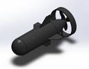

FINAL
CONCEPT(S)
After a process of elimination, we
arrived upon two final concepts. Model 1 uses a gyroscope method to
harvest energy. Model 2 utilizes a mass spring damper system to harvest energy.
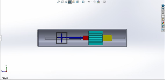
Figure 1: The present design consists
of a system whose main characteristic is the implementation of a gyroscope.
Theoretically, the gyroscope would move due to the movement of the waves.
Correspondingly, the mechanical movement of the gyroscope would be transformed
into electrical energy using a converter.
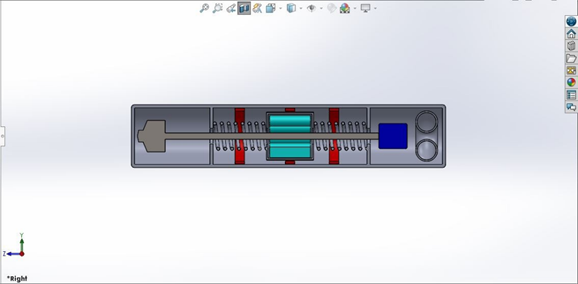
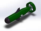
Figure 2: The second design implies
the implementation of a system which when moving with the mechanical energy of
the waves, the battery would generate an oscillatory movement which would
generate the recharge of the batteries by means of other compounds. The
electrical energy would be transmitted directly to the batteries.
The objective of the Embodiment
Design stage is to realize the concept previously designed.
STRATEGIES AND
PRIORITIES
Starting from our final concept, we
identified the necessary analysis and engineering work to realize the concept
into a product.
TASK 1: DECIDING
ENERGY HARVESTING METHOD
In order to
decide between the gyroscope method or the mass spring damper system, we did a
process of elimination. First, we
analyzed a gyroscope method previously used by Nicholas Townsend from the
University of Southampton.
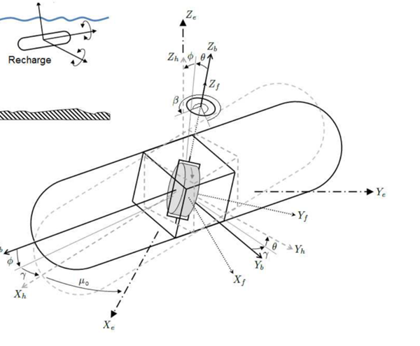
Figure: An Illustration of the
gyroscope system used in the model. [24]
Two studies in two different circumstances were done. One with high waves at a height of around .15m, the other with waves of around 0.1m. The power generated was then plotted and compared. [24]
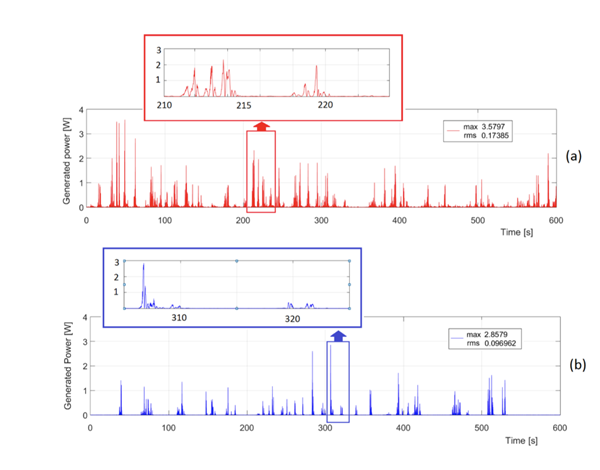
Figure: Power Generated in both
circumstances [24]
From the
figure above it can be observed that even though the maximum generated power is
promising, consistency is not there. As it can be seen there is moments were
power is not even generated.
A quick calculation of friction encountered during underwater
travel was done to determine how much power is needed to overcome it. [24]
Power = ((½)*Iyy*Wf^2)/t,
where (½)*Iyy*Wf^2 represents stored kinetic energy
& t=time for flywheel to slow down from 5100 rpm to 0
Power = (0.5*0.00482*(5000*2pi/60)^2)/710 = 0.9W
From this calculation it can be observed that
even at maximum power generated levels, which are rare, it takes almost 1/3 of
the power generated to overcome friction. [24]
After these results it was determined to stop
further developing this final concept. The efficiency of the gyroscope method
was not appealing at all. [24]
TASK 2: CREATE A DESIGN SKETCH
The team created a design sketch of what the assembly should
look like prior entering in the CAD design phase. This came alongside labeling
the distinct parts that will be required with the purpose of starting to make our
Purchas Approval Form.
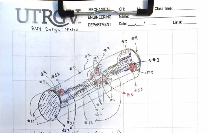
Figure: Design Sketch
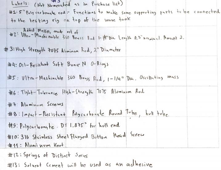
Figure: Part
Labeling
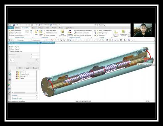
TASK 3: CREATING
A MORE DETAILED CAD OF OUR CHOSEN FINAL CONCEPT
After
finally arriving on our final concept, we had to bring this concept to reality. Here is how we did
it.

Figure: Detailed
CAD model using NX12 software
TASK 4:
DETERMINING HOW THICK THE HULL SHOULD BE
In order to
determine how thick, the hull should be we conducted finite element analysis on
the basic geometry of the hull. We did
the FEA analysis twice changing the thickness every time. We started at a thickness of 0.5
inches, followed by 0.2inches. We applied the load by using the
formula P = pgh +Patm. At a
depth of 100m, to be conservative. Where the density is 1030 kg/m^3,
gravity is 9.81 m/s^2, and pressure atmosphere is 101,325 Pascals. Therefore, the
hydrostatic pressure applied is 1,111,856 Pascals.
FEA ANALYSIS WITH THICKNESS 0F 0.2 INCHES
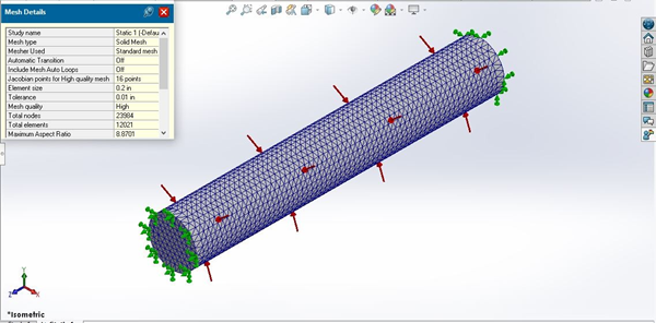
Figure: Mesh
created with a mesh size of 0.2 inches containing 12021 elements
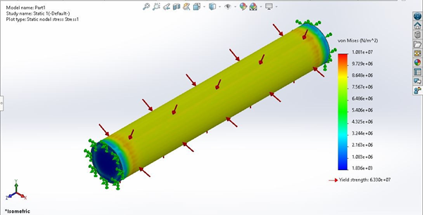
Figure: Stress Analysis
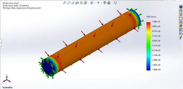
Figure: Deformation Analysis
The hull
suffered no deformation with a thickness of 0.2inches as it can be observed in
the figure above.
FEA ANALYSIS WITH THICKNESS OF 0.5
INCHES
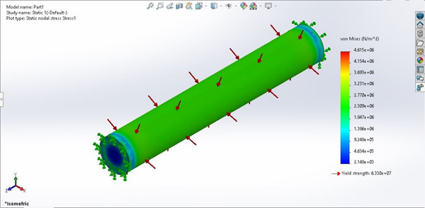
Figure: Stress Analysis

Figure: Deformation Analysis
Neither
thickness suffered no deformation. Therefore, it was decided to move
forward with a thickness of 0.2 inches in order to
conserve mass and resources.
TASK 5: STABILIZING AUV
As the
springs oscillate the mass, it is obvious that the AUV will not remain stable.
Causing it to tip over.
To combat this issue, it was determined that we must oscillate
the mass in two parts.
Each time keeping the mass oscillating on each side even. We will explain it
using illustrations. Pay
close attention to the center mass.
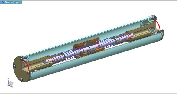
Figure : Stabilizing AUV
Figure: Stabilization of the AUV
Figure: Stabilization of the AUV
TASK 6:
USE MEASUREMENTS FOR DEVELOPMENT OF EARLY 3D PROTOTYPES
After making
the necessary design sketches, the appropriate 3D CAD designs, and acquiring
the necessary measurements, the team proceeded to create its first 3D
prototype. As we can appreciate the prototype its on
early stages of development, but the assembly of the parts required results
successful. This will help the team have a better point of view regarding how
to proceed in the next task.
Figure: Overall
view
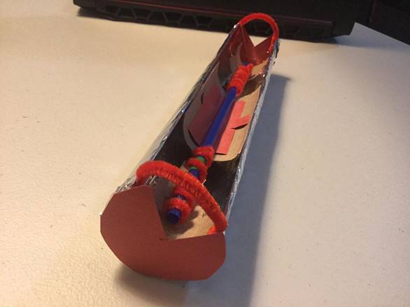
Figure: Rear view
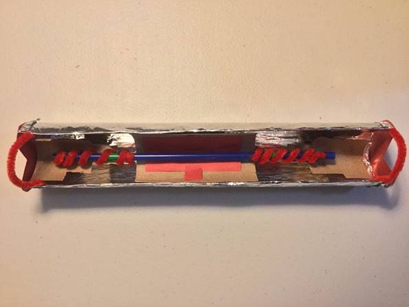
Figure: Top view
TASK 7: PREVENTING
WATER FROM LEAKING ON AUV
Water leaks
will be prevented using an O-ring. Rubber is used to make these bits. Two
aluminum parts will be mounted on either end of the AUV using the appropriate
screws, sealing the AUV and stopping water from entering. These components will
be machined in accordance with the requirements.
TASK 8:
CREATING A DAMPER
The
oscillatory movement in the central mass is caused by the mechanical movement
of the waves in combination with the stainless steel, causing the aluminum rods
to go up and down like a piston. When this is combined with the aluminum
chamber built to the design specifications, a damper is made. Air would be
pushed into the chamber by the aluminum rod, causing resistance.
TASK 9:
CONTROLLING THE DAMPING COEFFICIENT
We made the observation that the air pushed into the chamber
may create an exaggerated damping coefficient resistance. Making it difficult for the springs to operate. In order to control
this issue a hole will be drilled on each side of the chamber. Each hole will have an integrated release
system for best optimization of the damping coefficient.
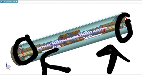
Figure: Release system
TASK 10:
OPTIMIZING OSCILLATE PERFORMANCE
To optimize
oscillate performance, different spring sets can be used on the design,
allowing the best spring constant to be used based on the desired performance.
Two disk springs are used to shield the parts and improve the bouncing
movement.
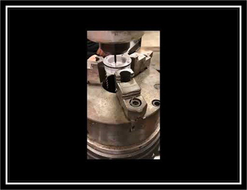
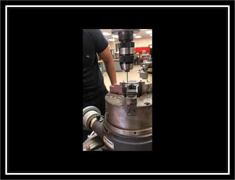
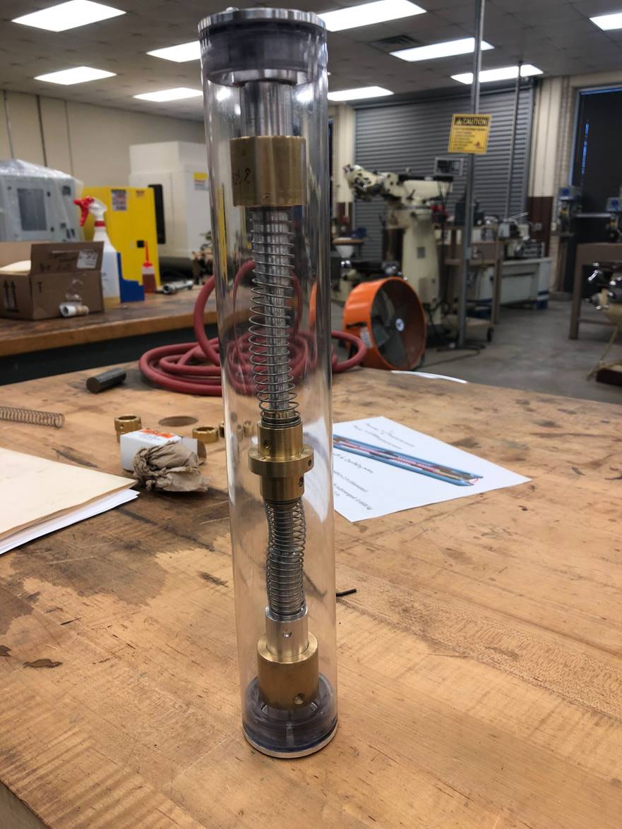
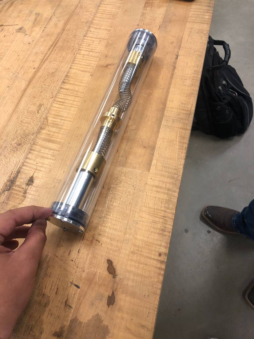
MACHINING PROCESSES
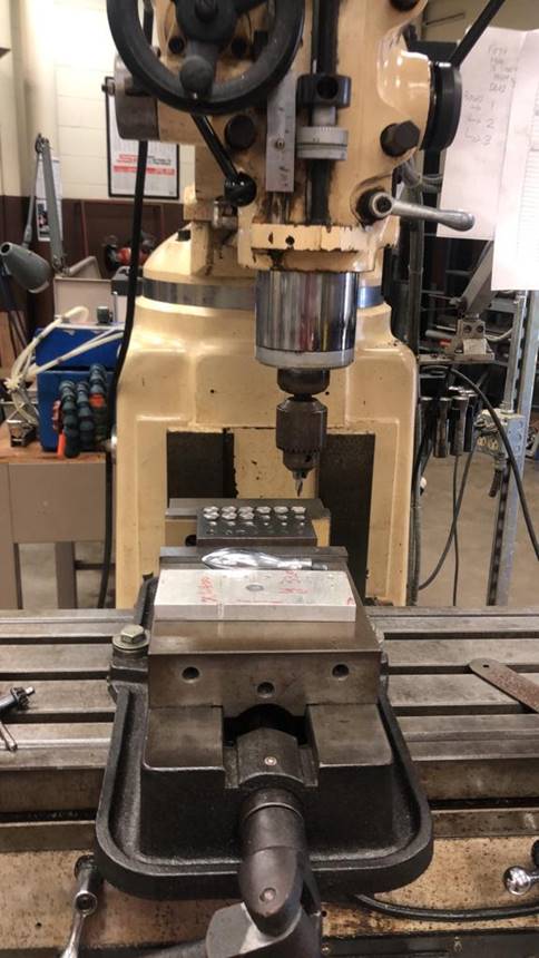
Above we can appreciate the machining
process for the parts of the AUV which use the following material:
Ultra-Machinable 360 Brass, High-Strength 7075 Aluminum, and Polycarbonate.
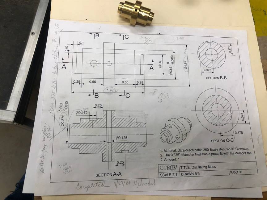
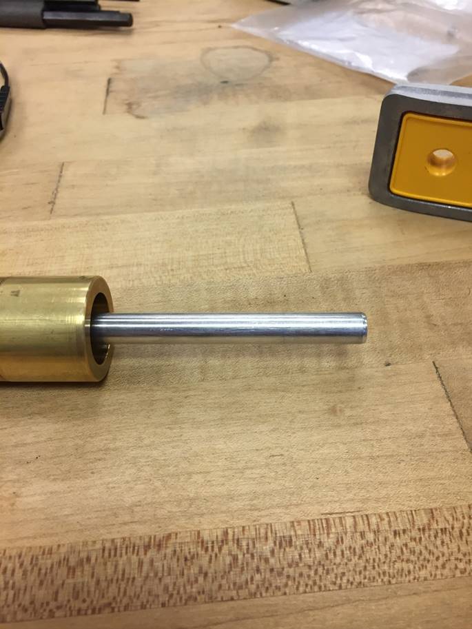
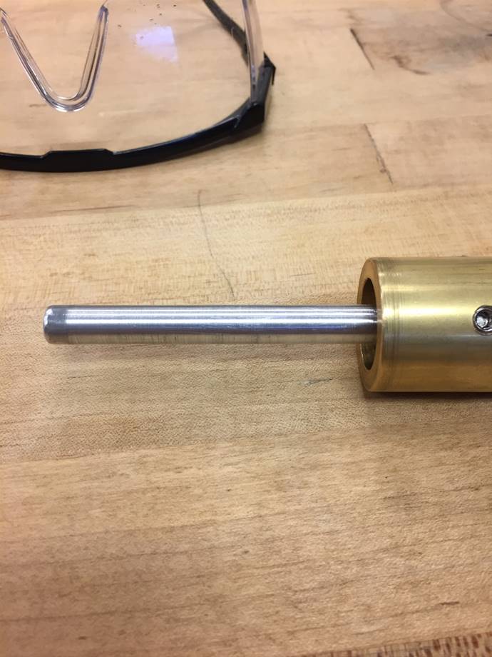
The presented piece is an oscillating
mass made of Ultra-Machinable 360 Brass. The oscillating mass is a central
component of the AUV, and its function is to oscillate with the movement of the
waves. It’s 0.375 ‘’ hole has a press fit with the damper rod, and a total
length of 1.9’’.
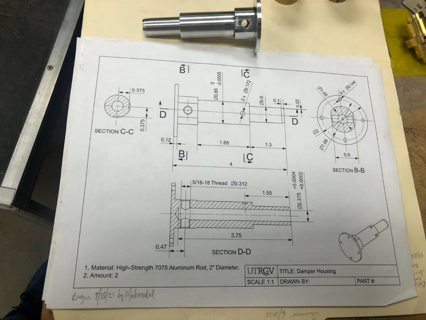
The damper housing is made of
high-strength 7075 aluminum, and its function is to work as a damper. The holes
on this piece are meant to regulate the compressed air. The total length of
this piece is 4’’ and a outside diameter of 2’’.

The following two pieces are
components of added mass 1. These parts are made of Ultra-Machinable 360 Brass,
with the main function to facilitate the oscillatory movement of the
oscillatory mass. The total length of each of the pieces are 0.9’’ and a outside diameter and inner diameter of 1.25’’ and 0.85’’
respectively.
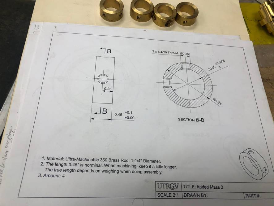
The four machined parts presents are
made of Ultra-Machinable 360 Brass and are components of added mass 2. The
purpose of creating both added masses is to find the perfect combination to
improve the oscillatory movement of the center mass in a more efficient way.
The length of each piece is 0.45’’ and an outside diameter and inner diameter
of 1.25’’ and 0.85’’ respectively.
Shown above we can appreciate the
blueprints for the distinct AUV parts that were machined through the Summer.
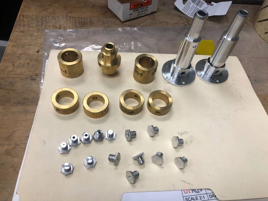
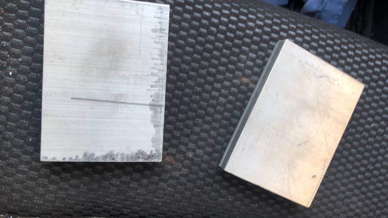
Above we can appreciate the finalized
machined parts necessary for the assembly of the AUV. The parts machined
included the following: Ultra-Machinable 360 Brass, High-Strength 7075
Aluminum, and Polycarbonate.
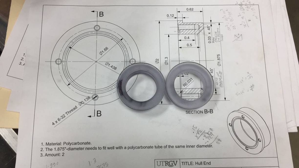
The following part is made of
polycarbonate, and its function is to seal the AUV by connecting it against the
damper housing. The outside diameter of the piece is 2’’, with an inside
diameter of 1.3’’.
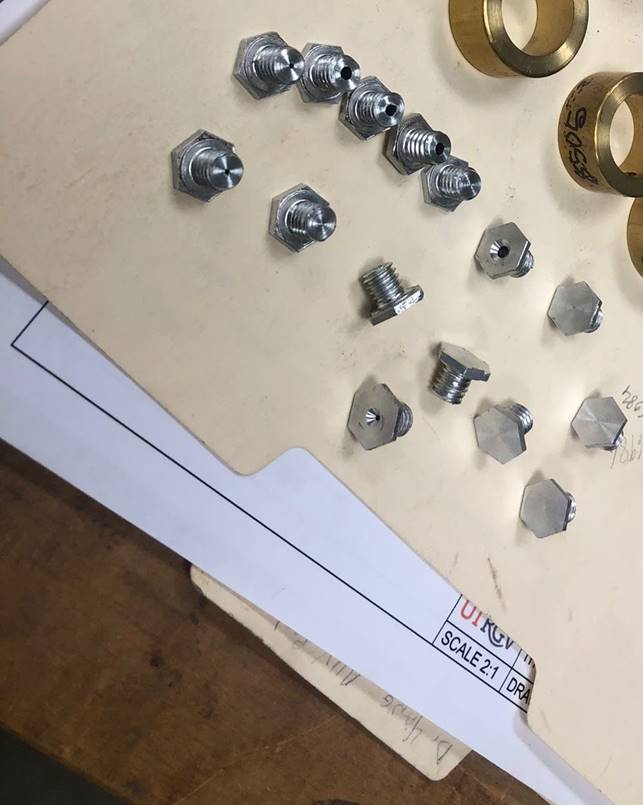
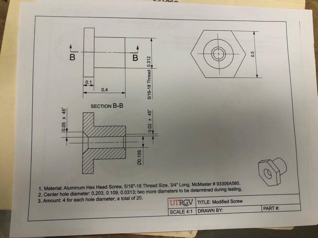
Presented above are the machined
aluminum screws, which are going to be implemented as an escape valve in order to regulate the compressed air in the damper
housing. There are 5 sets of screws, each set has a different center hole
diameter in order to find the correct combination for
a more efficient performance.
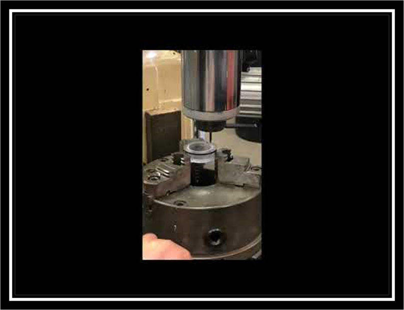
Shown above we can appreciate the
machining process required for the Polycarbonate, creating the end caps
necessary for the AUV.
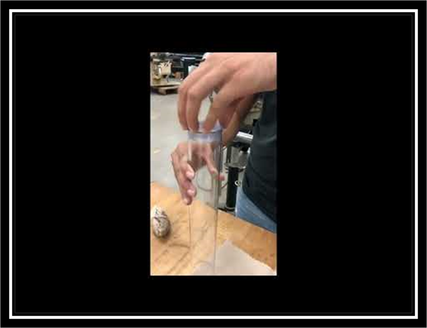
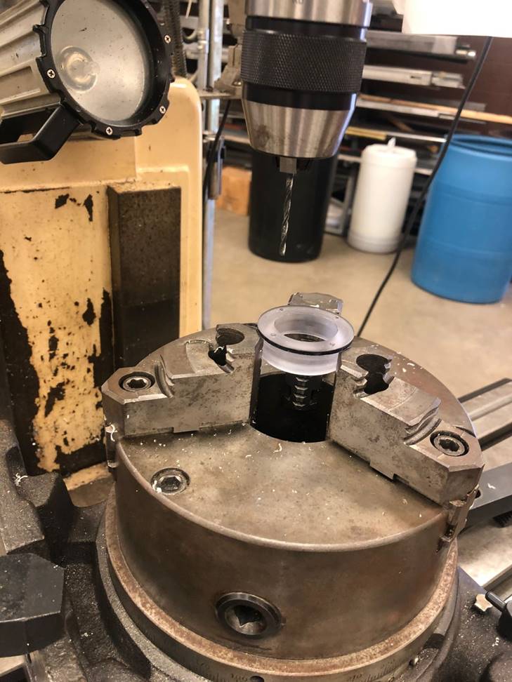
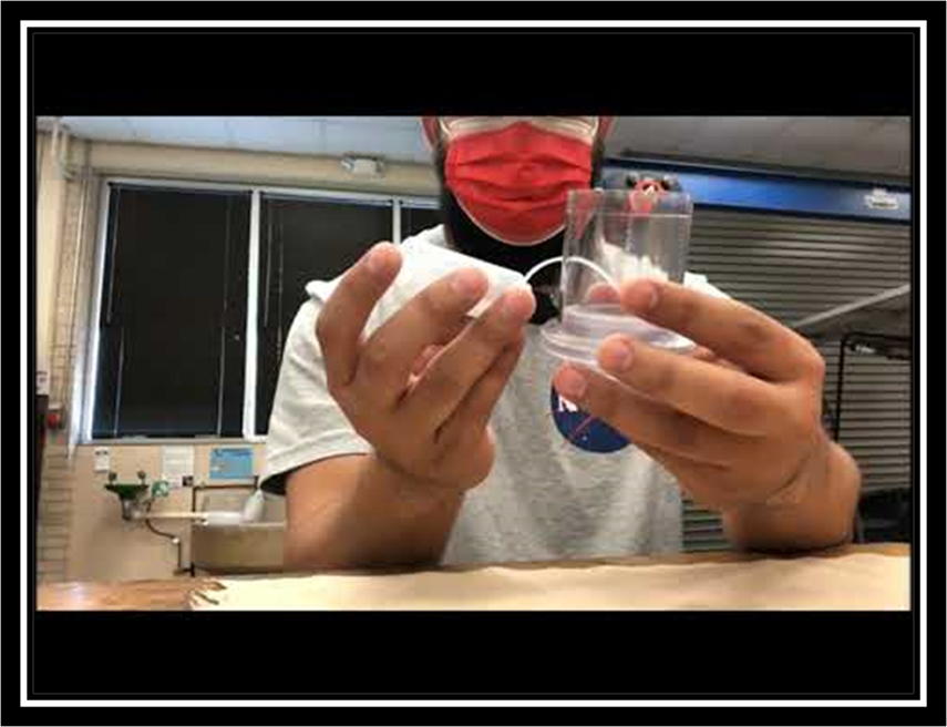
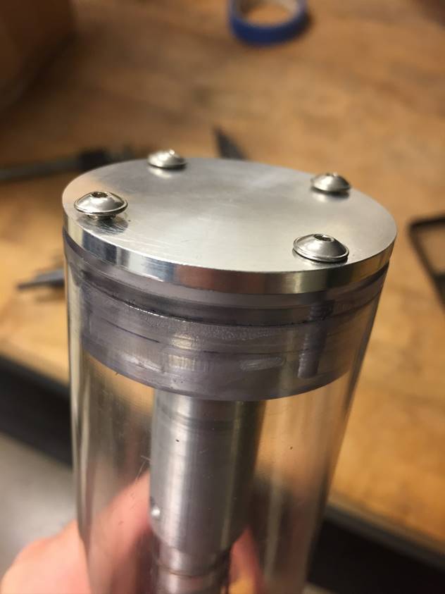
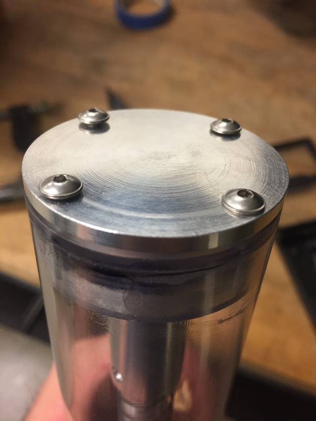
Above we can appreciate the fit testing
process of the AUV caps, as well as the fit and placement of the O-rings before
proceeding with the application of the adhesive cement.
One of the challenges faced while
practicing the application of the adhesive cement was that if this process was
not done properly and did not cover the entire surface, as well as if it was
not given the proper time to dry this could lead into it breaking the piece and
detaching from the surface when force was applied towards it.
Items used for fixing the
polycarbonate ends.
The process of testing how the
adhesive cement works was done in order to prevent any
mistakes at the actual time of applying it to our finalized AUV model, and that
is shown above. We can also appreciate the final application of the adhesive
cement to the AUV model, with the purpose of achieving a snugger fit.
In the images shown above we can find
a visual representation of the AUV model, which demonstrate the assembly
process.
Mount and
Connector Footprints
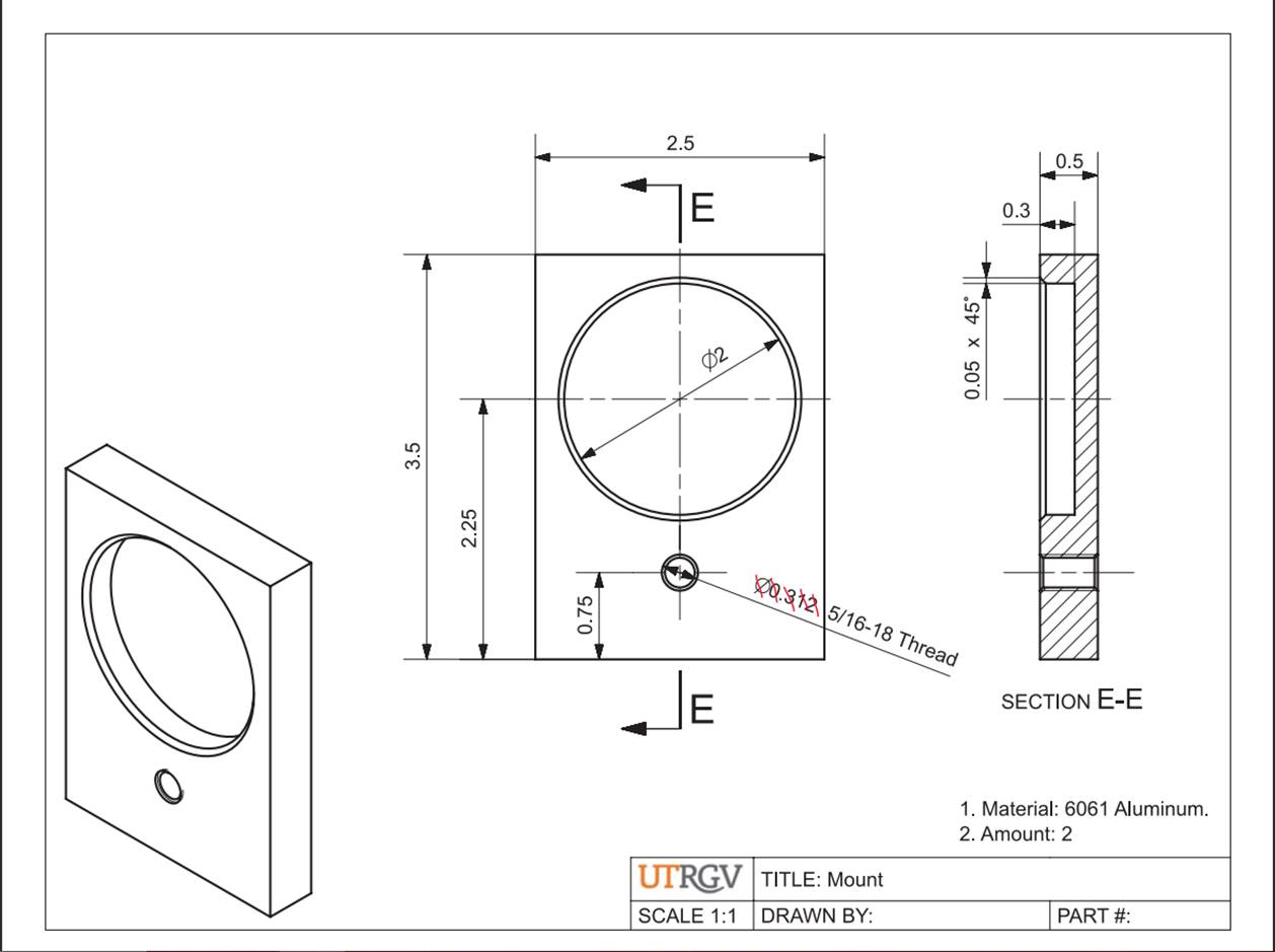
In the image shown below we can see
the footprint for the mount piece. This mount piece has been decided to be made
of 6061 Aluminum.
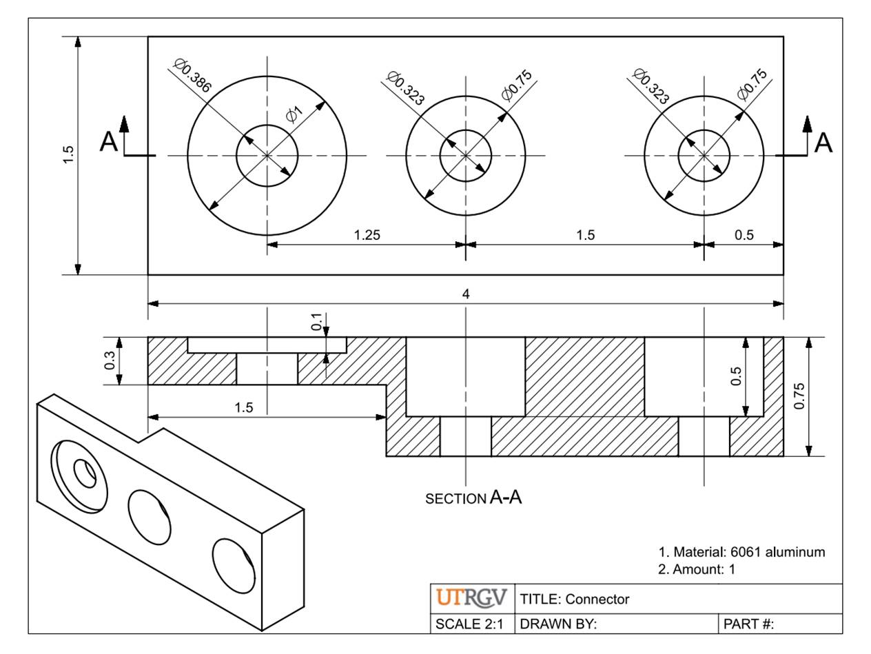

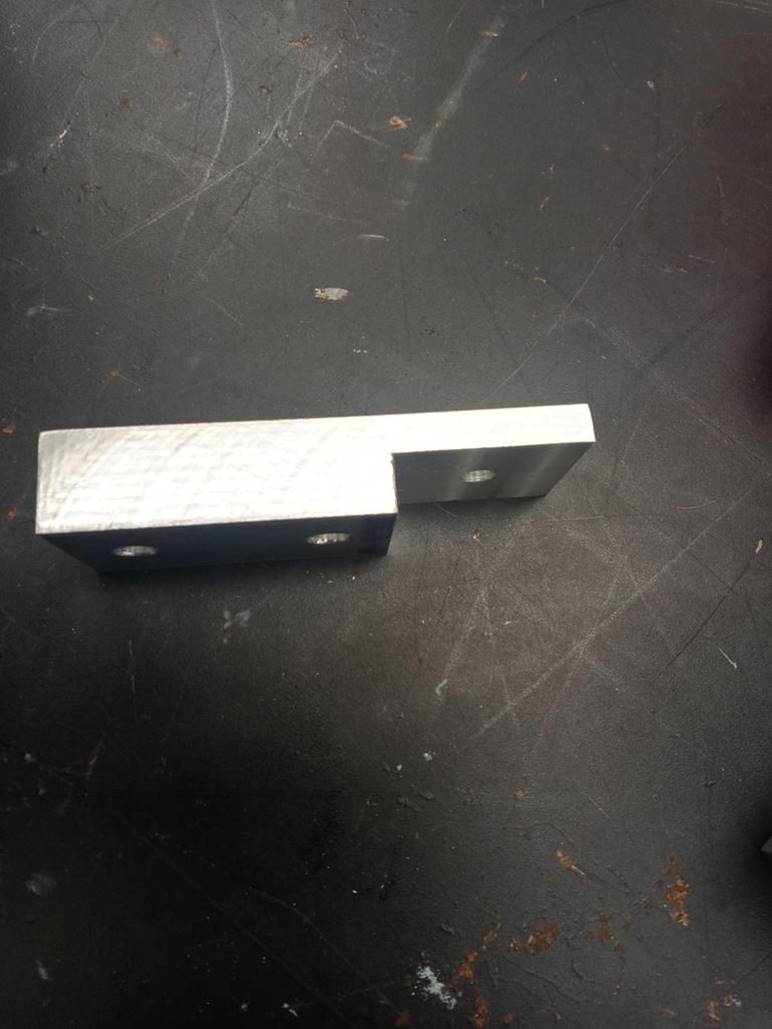
In the image shown below we can see
the footprint for the connector piece. This mount piece has been decided to be
made of 6061 Aluminum.
AUV Camera
Mount
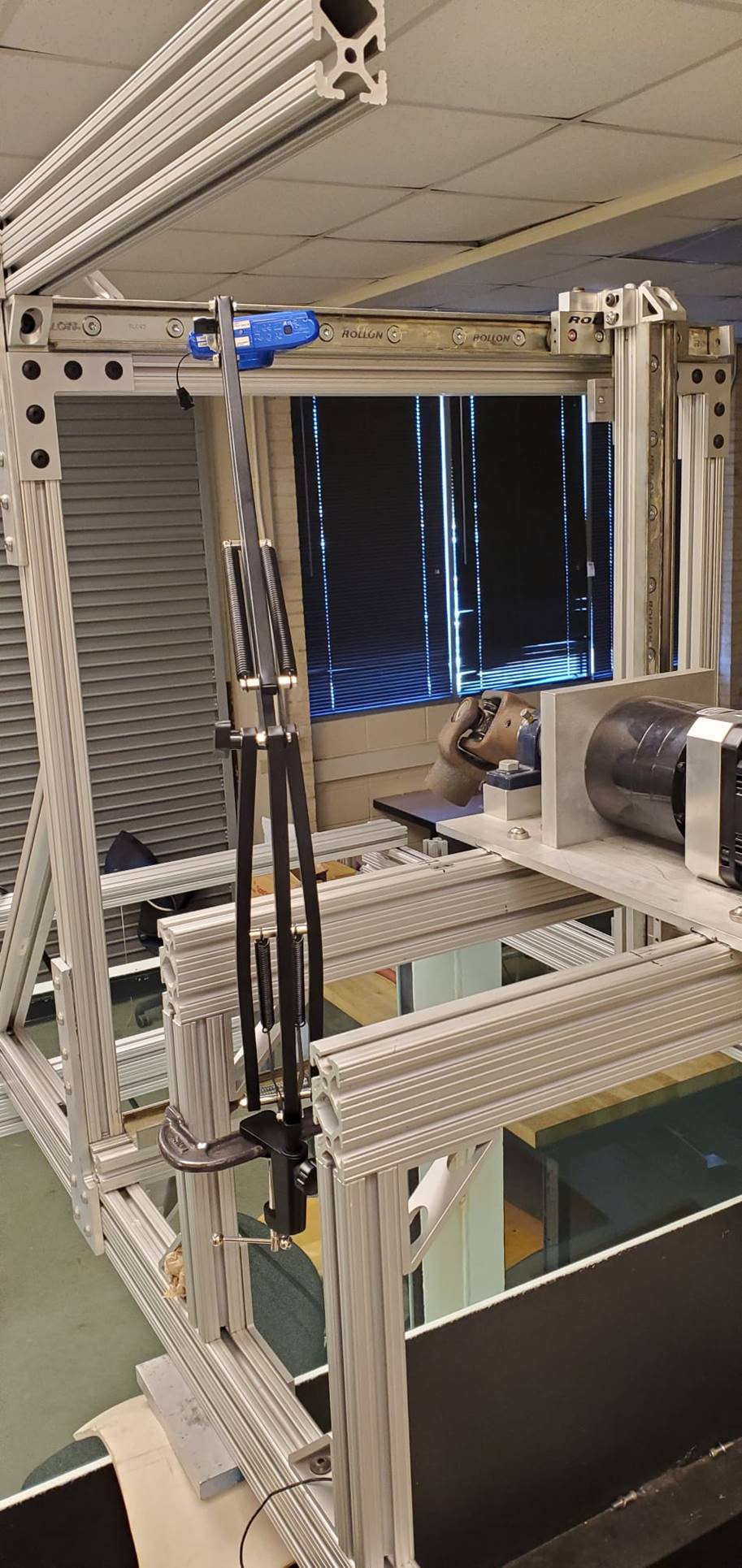
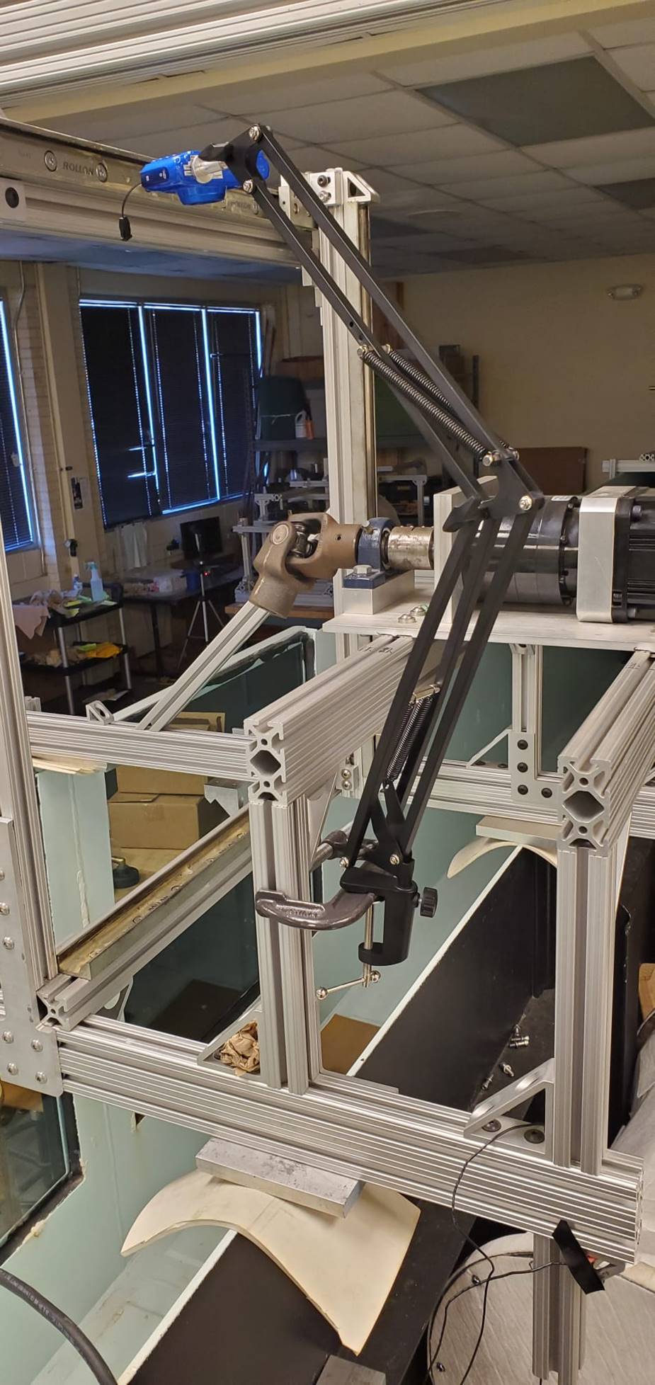
Team installed a Camera system to
observe movement of the oscillatory mass inside the AUV. Currently camera is
mounted to a fixed beam. In the future team will have to mount camera to a
moving beam so AUV can be observed as it moves about the x,y,z plane.
Assembly
Challenges
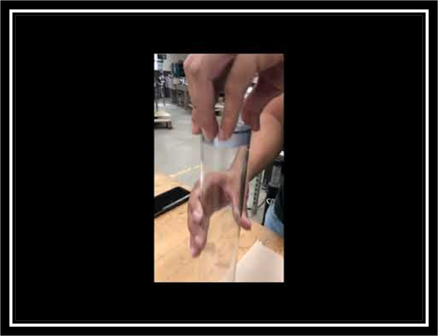
A challenge the team is
facing is that after assembling the AUV caps and tightening them up, the mass
does not move as expected. As you can appreciate in the images above, to solve
this issue the team loosen up the screws in the AUV and this are the results we
obtained. As you can observe the mass does move but not very smoothly, and we
are afraid this can cause some leakage to happen too.
After showing
results to Dr. Yang, we understood that loosening
up is just the first step. The team needs to fasten the screws again. But we
must fasten them correctly to achieve a good alignment for a smooth
oscillation. We will have to try it over and over again
in different ways to fasten them until we achieve the expected performance.
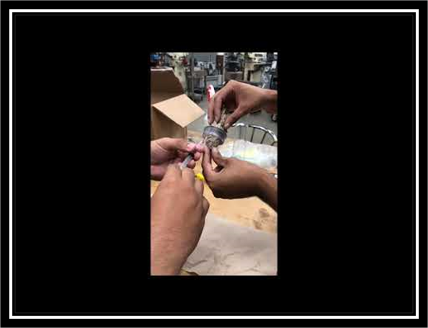
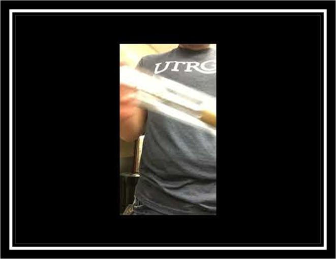
In the video shown above, we tried to
troubleshoot for the reasoning behind why the rod does not run as smoothly as
expected. The latest hypothesis is that as we can see in the image one end of
the rod was not filed correctly. In the first part of the video, we see the
side of the rod that was filed all the way through, and it slides smoothly when
compared to the second part of the video where when testing the other side of
the rod we can see the opposite.
ANALYSIS
The team in association with Dr. Yang decided that it was
better to concentrate in the damper mechanism for this project, for which
reason we will not be able to collect the data of how much energy it generates,
instead will concentrate in the theory side of the project. The team would
consider the mechanism to work properly if the energy generated by the waves
shows the damper mechanism to work as expect by creating a transversal movement
that should generate the power necessary.
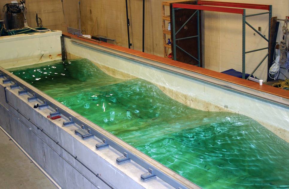
Simulation
As part of the simulation process, the team has planned to
use Dr. Yang’s water tank at the Machine Shop located in the Brownsville
campus. The water tank will provide a similar environment as the one that we
are seeking to use the AUV at, since it provides artificially generated waves
that will help us show how the damper turns the kinetic energy into power. This
mechanism has proved to properly function when assembling in NX 12, but we will
ensure that this is possible through multiple tests in the water tank once the
assembly of the AUV concludes.
FMEA:
Failure Modes and Effects Analysis
|
|
|
|
|
FAILURE MODE AND EFFECTS ANALYSIS |
|
|
|
|
|||||||
|
Item: |
AUV |
Responsibility: |
Team 8 |
|
FMEA number: |
N/A |
|||||||||
|
Model: |
Model 1 |
Prepared by: |
Team 8 |
|
Page : |
N/A |
|||||||||
|
Core Team: |
SDII |
|
FMEA Date (Orig): |
9/16/2021 |
Rev: |
1 |
|||||||||
|
|
|
|
|
|
|
|
|
|
|
|
|
|
|
|
|
|
Process Function |
Potential Failure Mode |
Potential Effect(s) of Failure |
Sev |
Potential Cause(s)/ Mechanism(s) of Failure |
Occur |
Current |
Detec |
RPN |
Recommended Action(s) |
Responsibility and Target Completion Date |
Action Results |
||||
|
Actions Taken |
Sev |
Occ |
Det |
RPN |
|||||||||||
|
Housing of AUV |
Leakage |
The vehicle will sink and therefore stop working. |
10 |
If the housing gets damaged while shipping or in the assembly processes. |
6 |
Assemble an O-ring, made out of rubber. Two aluminum parts will be mounted on either end of the AUV using the appropriate screws, sealing the AUV and stopping water from entering. |
8 |
480 |
The assembly of the O-ring, as well as to use safety methods of shipping to the user in order for it to arrive without any damage that can lead to leakage. |
Assembly Engineer / Shipping Method |
Use of High-Strength 7075 Aluminum Rod to avoid easily get damaged |
8 |
6 |
8 |
384 |
|
Magnets to hold battery in place |
Demagnetize the magnet, making the battery to lose its place and stop the process of storing energy. |
Leave the AUV out of power, which can result in it to get lost depending where it is at the moment. |
9 |
If it gets close to a strong magnetic field of opposite polarity the magnets inside can be demagnetize. |
4 |
Give a proper instruction manual, specifying the possible effects of not storing it properly. Also, provide a special case that can neglect outside magnetic fields from affecting the magnets. |
8 |
288 |
Providing the user with an special carrying case that avoids external magnetic fields of opposite polarity. |
Design Engineer |
Development of a detailed instruction manual in order to avoid these issues. As well as to seek materials that can be used as isolating materials in the carrying case the AUV requires. |
8 |
4 |
8 |
256 |
QFD
(Quality Function Deployment)
QFD is a mechanism to ensure that the customer needs drive
the entire product design and production process in the company, including
market planning, product design and engineering, process development and
prototype evaluation, as well as production, sales, and service.
|
Customer Quality Experience |
Design Spec |
Critical Function(s) |
Component(s) |
|
Reliable method for transportation
of material underwater. |
Possibility of creating a cavity to
serve as storage for research material. |
Need to find a way in which at the
time of storing the material we will not let any leakage enter the system. |
Storing space inside AUV housing. |
|
Have an unlimited source of energy,
while at the same time not running out of power. |
Create a renewable source of energy
via a damper mechanism, which will provide energy through the kinetic energy
obtained with the motion of the waves. |
The damper mechanism is custom made
by the team, therefore if we plan to make multiple, we need to make sure all
the measurements are the same because if not this can lead it to not work properly. |
Custom damper mechanism assembled
by team. |
|
Capable of reaching underwater
ground levels, which for people it is hard to achieve due to high pressures. |
Made a design that makes use of
O-rings in the extremes of the AUV in order to avoid
any type of leak due to the high pressure. |
Need to verify that the O-rings fit
the caps properly on both sides of the AUV. |
O-rings. |
Potential Customers
Early on the following AUVs were designated as competitors,
however we then identified them as potential customers due to their limitations
when recharging. All
of these AUVs take up resources by having to be retracted from their
mission to be charged. Our design would
improve all of them.
1. Teledyne Marine
2. RTSYS
3. Tiburon Subsea
4. Kongsberg
Hands on
Analysis
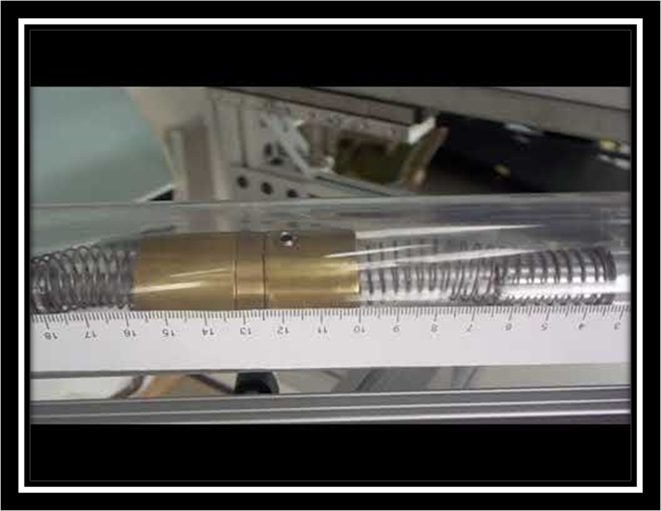
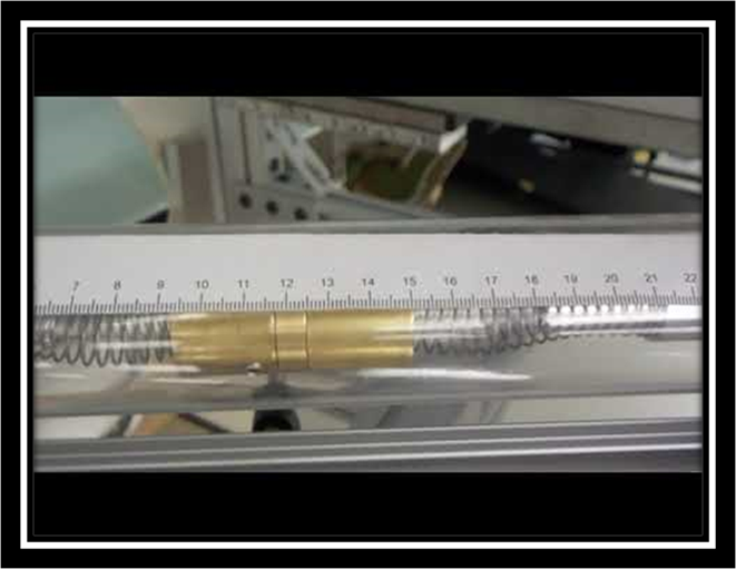
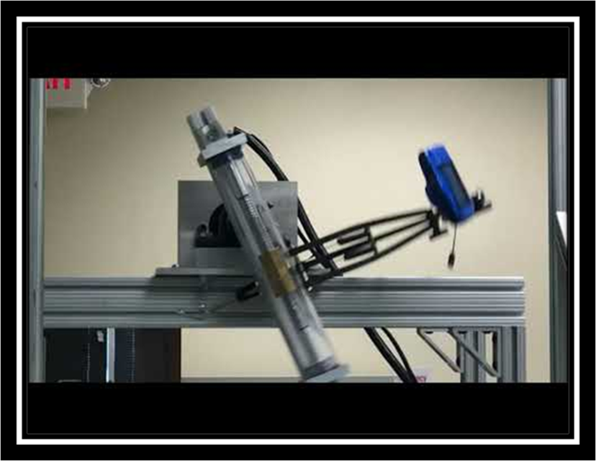
This video illustrates the
oscillation of the mass when subjected to the following parameters: Gear pulse:
6, set point: -7000 to 7000, Velocity: 180 rpm. All tests were done with the AUV
inclined at an angle of 75 degrees to ease the movement of the mass. The ruler is in cm.
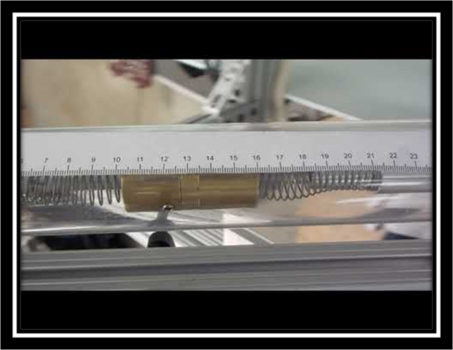
This video illustrates the oscillation
of the mass when subjected to the following parameters: Gear pulse: 6, set
point: -7000 to 7000, Velocity: 250 rpm. All tests were done with the AUV
inclined at an angle of 75 degrees to ease the movement of the mass. The ruler
is in cm.
This video illustrates the
oscillation of the mass when subjected to the following parameters: gear pulse: 6, set point: -7000 to
7000, velocity: 300 rpm. All tests were done with the AUV inclined at an angle
of 75 degrees to ease the movement of the mass. The ruler is in cm.
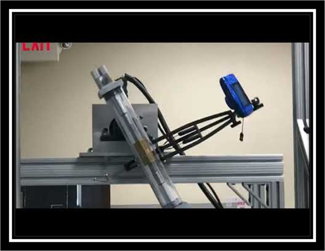
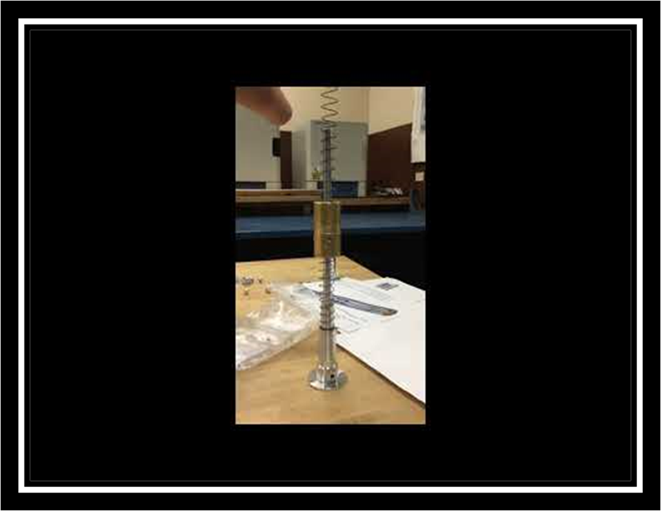
A different view of how the whole
system works. In this video the AUV was subjected to the following parameters: Velocity:
180, Gear pulse: 6, set point 7,000, also
in this view you can observe how the integrated camera system functions to give
a better observation of the mass. Behind it you can also see the motor setup. Giving
a better feel of how the overall system is working.
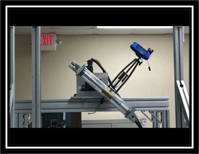
A different view of how the whole
system works. In this video the AUV was subjected to the following parameters: Velocity:
250, Gear pulse: 6, set point 7,000, also in this view you can observe how the
integrated camera system functions to give a better observation of the mass.
Behind it you can also see the motor setup. Giving a better feel of how the
overall system is working.
A different view of how the whole
system works. In this video the AUV was subjected to the following parameters: Velocity:
360, gear pulse: 6, set point: 7,000, also
in this view you can observe how the integrated camera system functions to give
a better observation of the mass. Behind it you can also see the motor setup.
Giving a better feel of how the overall system is working.
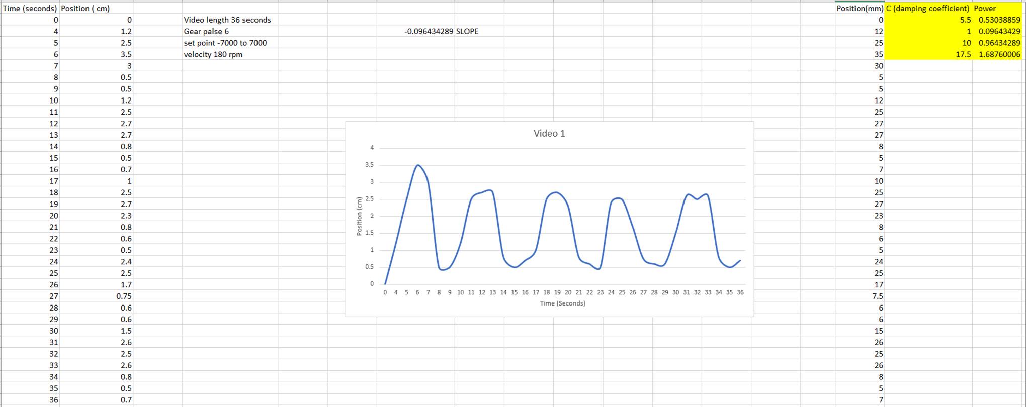
The graph above illustrates the
behavior of the oscillating mass when subjected to conditions of velocity: 180
rpm, gear palse: 6, setpoint: -7000 to 7000. After plotting the graph, we
determined the slope, which is the avg velocity. After obtaining the velocity
we determined the power by using the following formula. Power = damping
coefficient * velocity
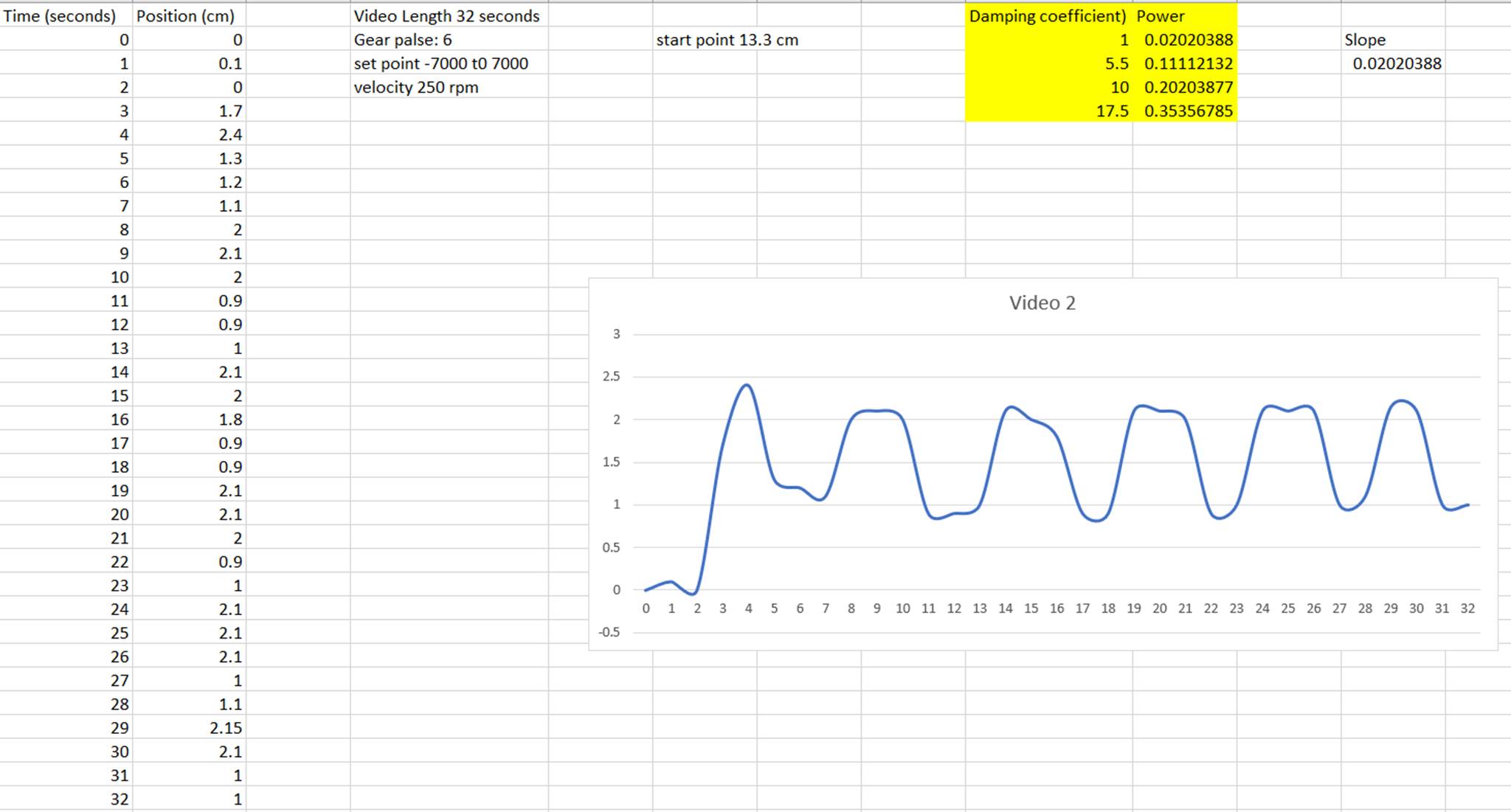
The graph above illustrates the
behavior of the oscillating mass when subjected to conditions of velocity: 250
rpm, gear palse: 6, setpoint: -7000 to 7000. After plotting the graph, we
determined the slope, which is the avg velocity. After obtaining the velocity
we determined the power by using the following formula. Power = damping
coefficient * velocity
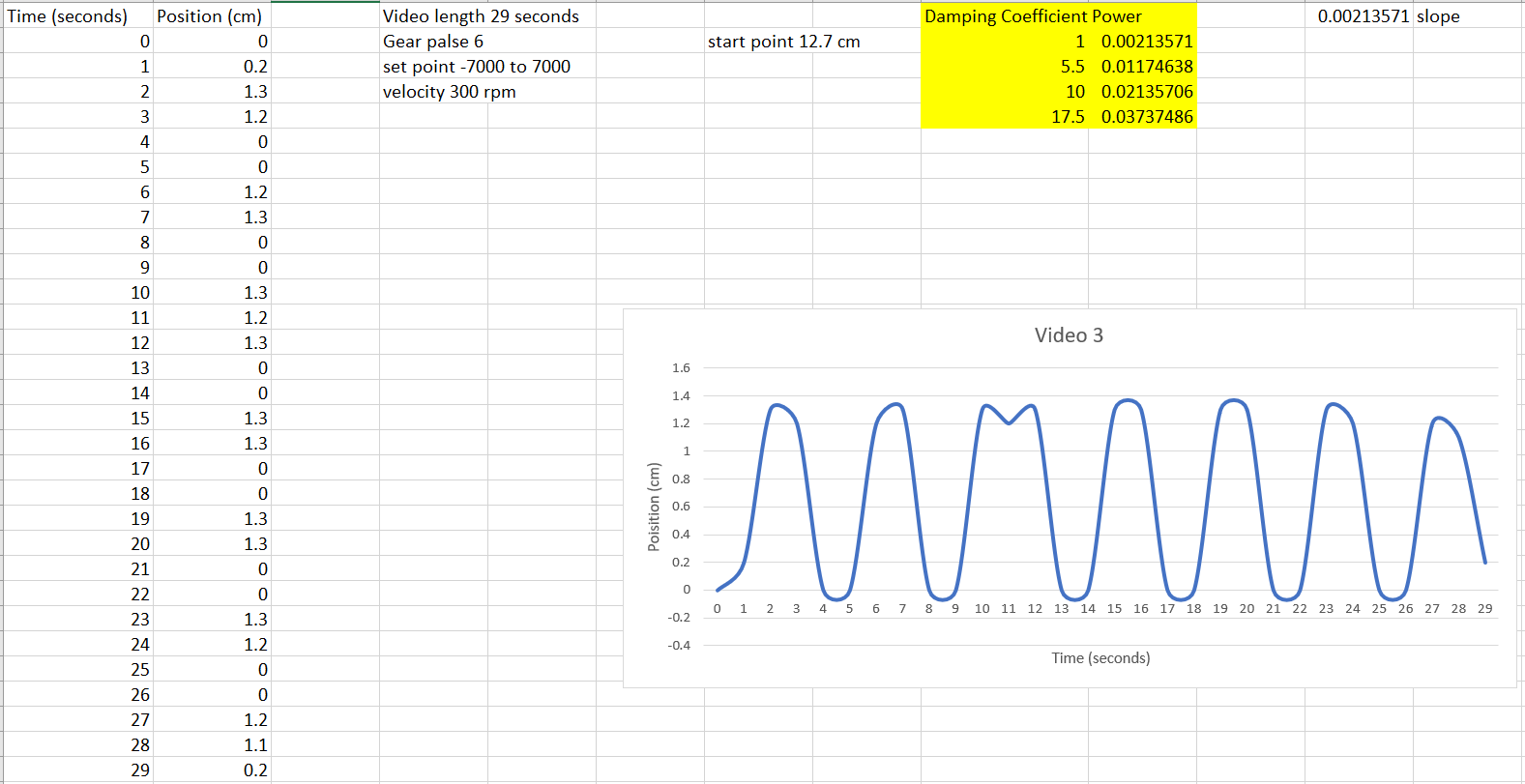
The graph above illustrates the
behavior of the oscillating mass when subjected to conditions of velocity: 300
rpm, gear palse: 6, setpoint: -7000 to 7000. After plotting the graph, we
determined the slope, which is the avg velocity. After obtaining the velocity
we determined the power by using the following formula. Power = damping
coefficient * velocity
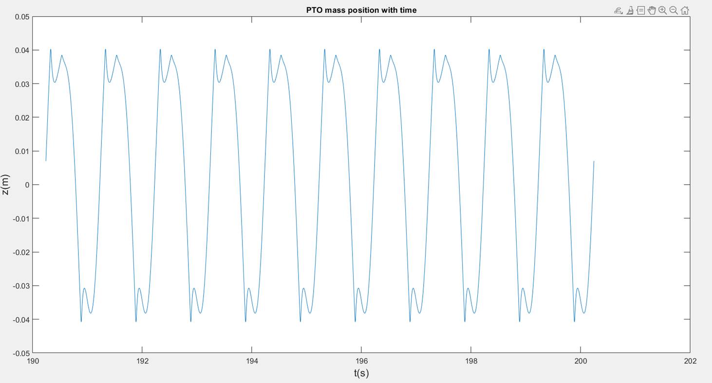
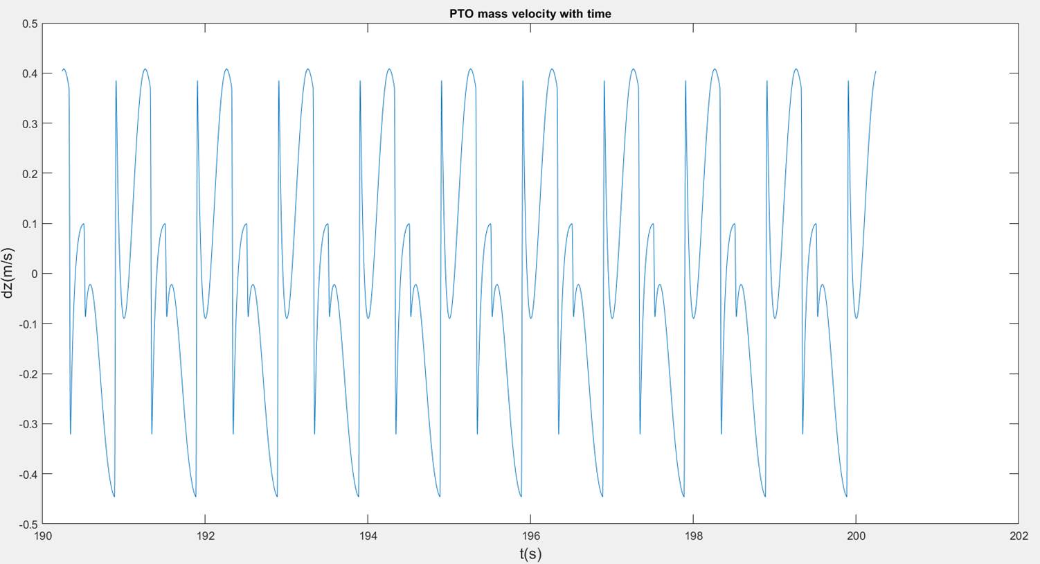
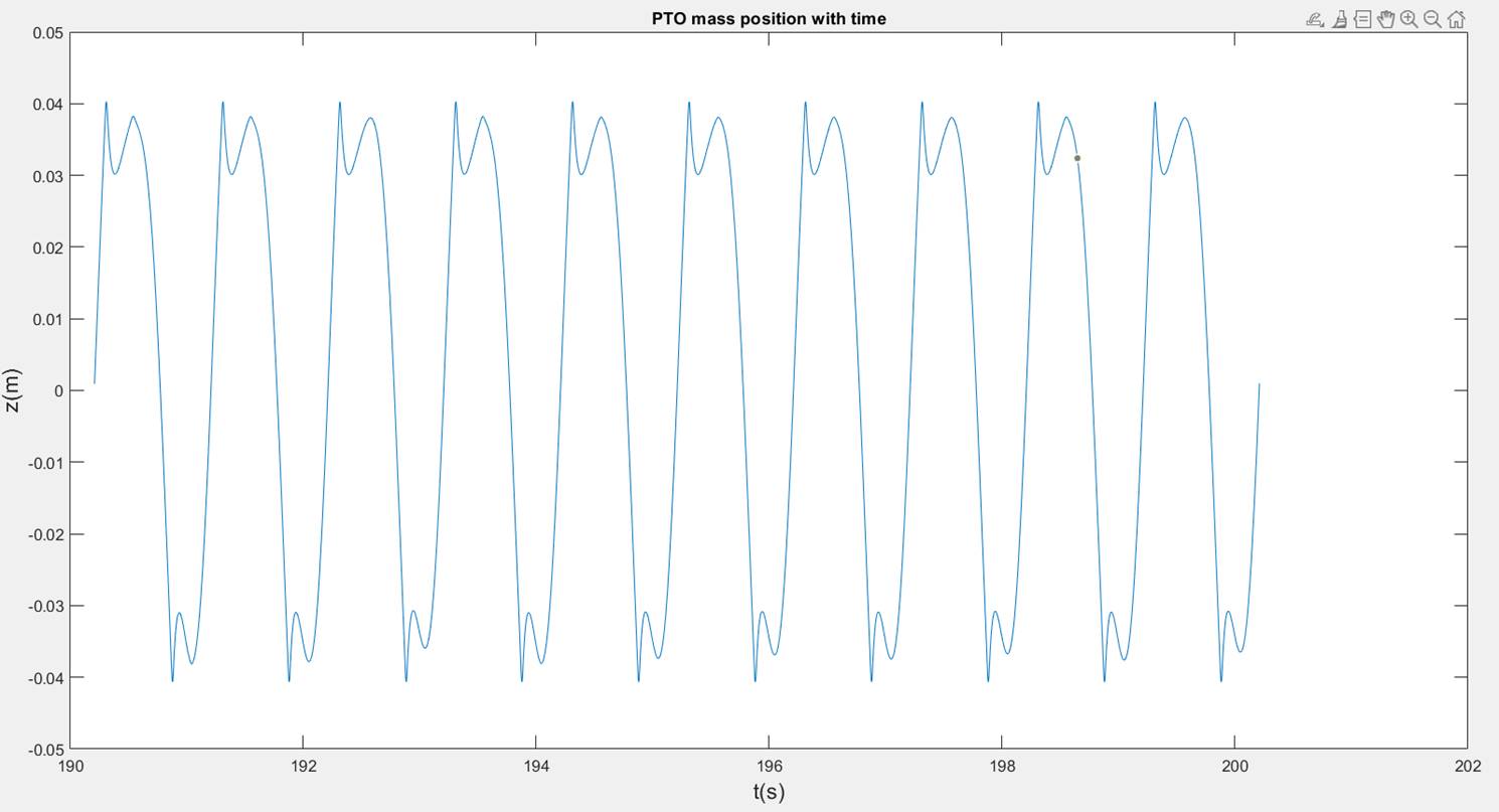
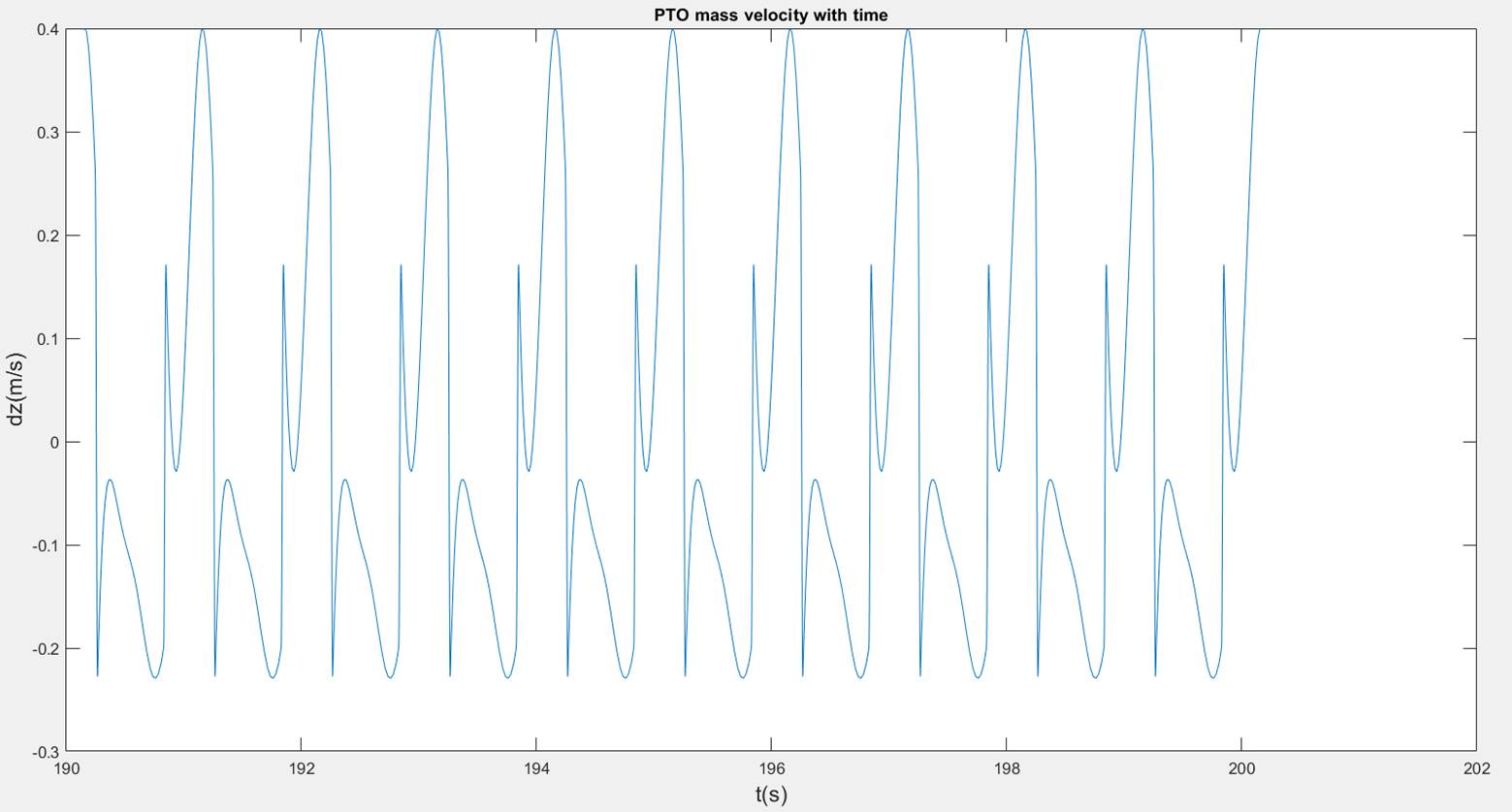
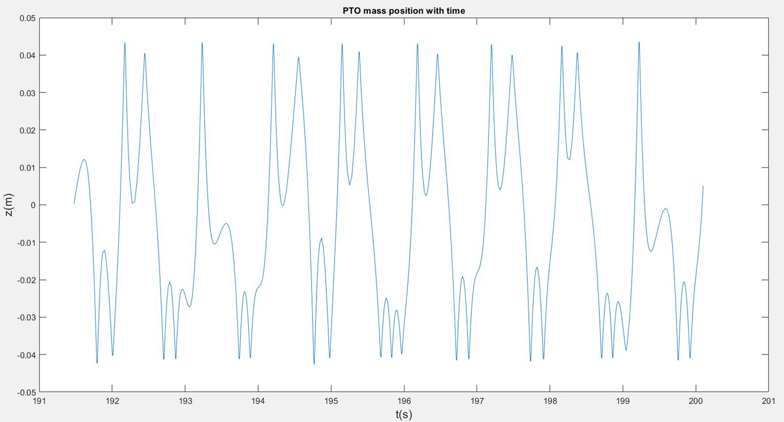
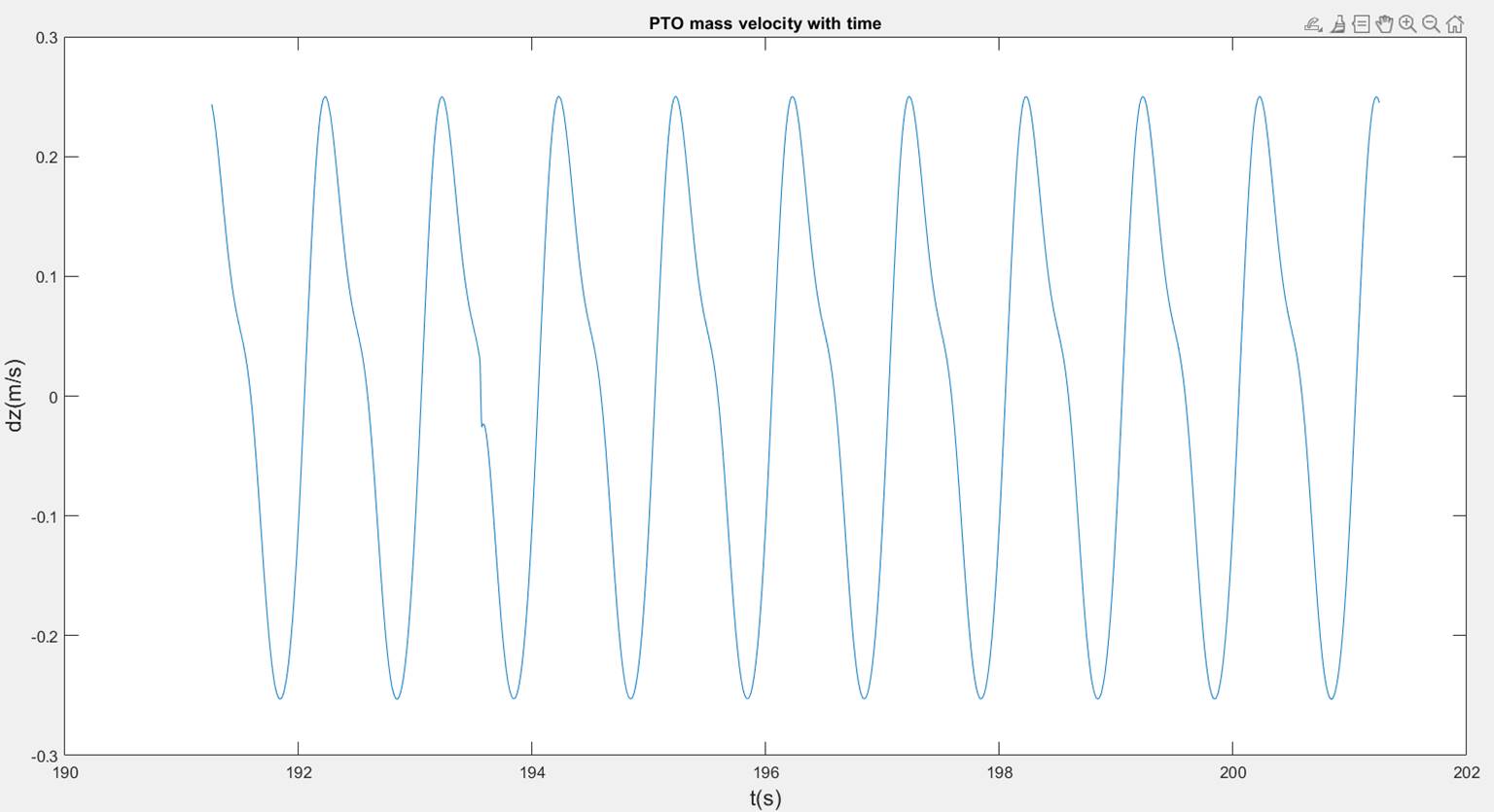
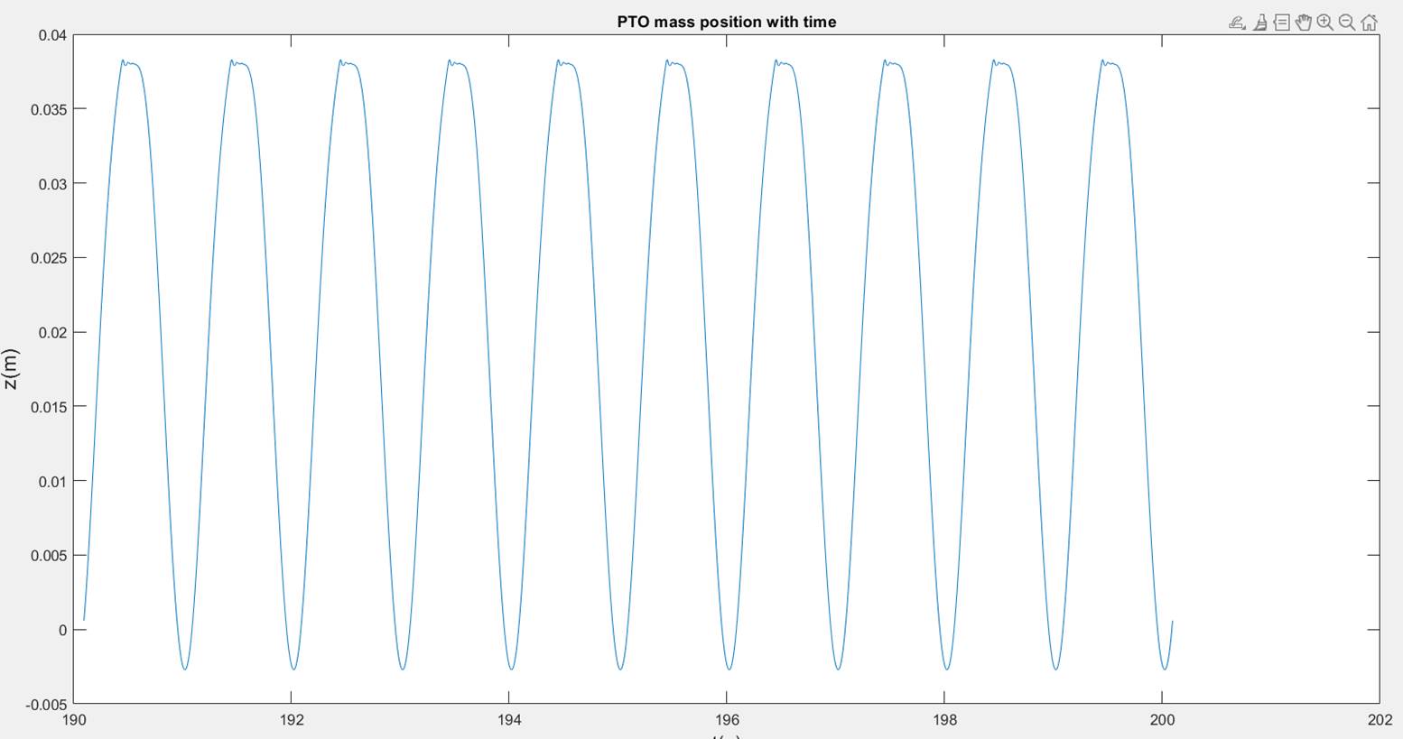
Power and Time Plots for Reduced
Model
Parameters
used:
Gravitational
acceleration, g = 9.81 m/![]() ;
;
Wave
frequency, ![]() = 1 Hz;
= 1 Hz;
Wave height,
H = 0.2 m;
AUV
oscillation amplitude, theta = pi/3;
Phase angle,
phi = 0;
Power
take-off (PTO) mass, m = 0.357 Kg;
PTO mass
stroke, z0 = 0.038 m;
Disk spring
parameter, n = 100;
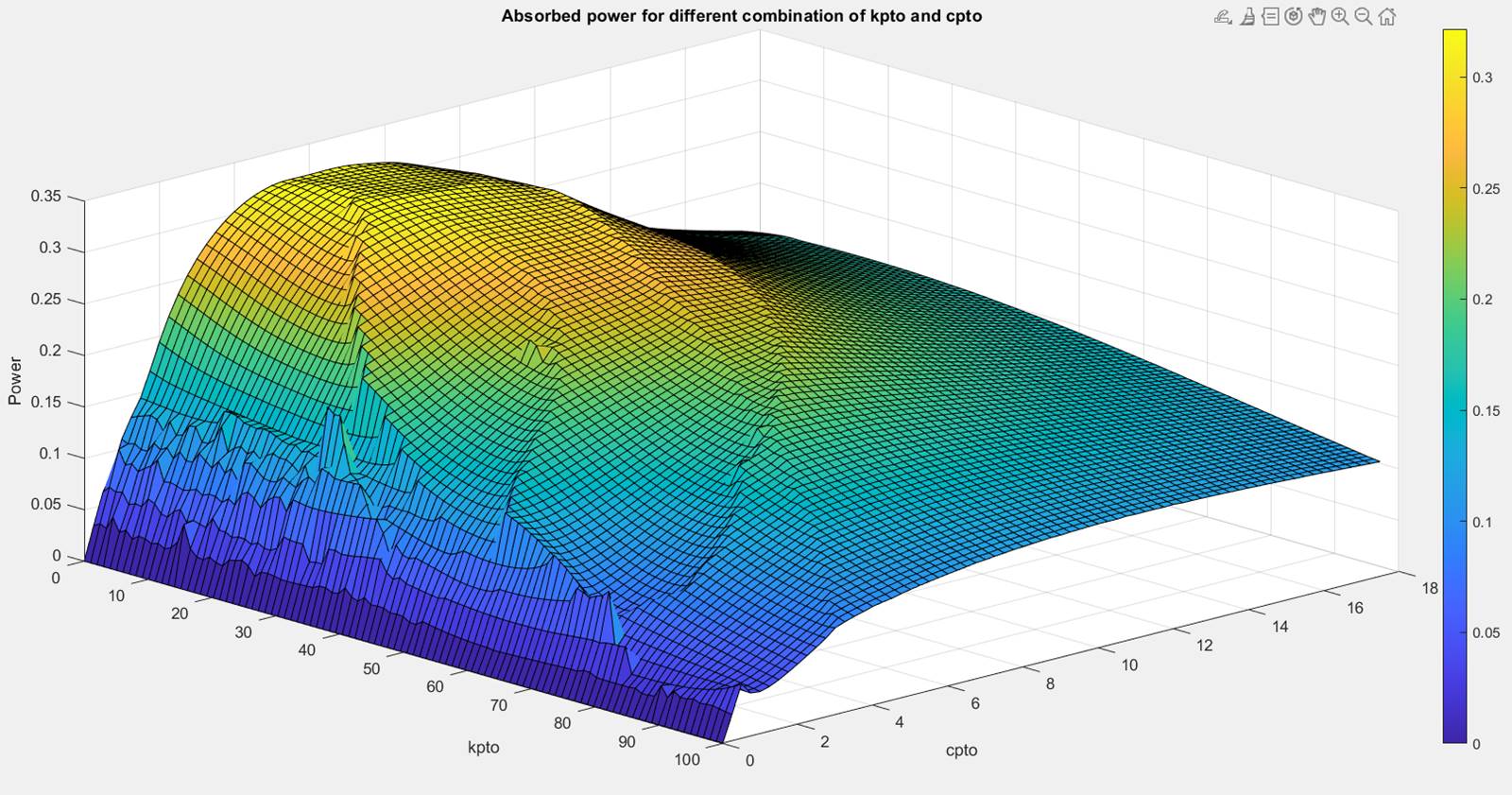
![]()
Absorbed
power, P = 0.3215 W
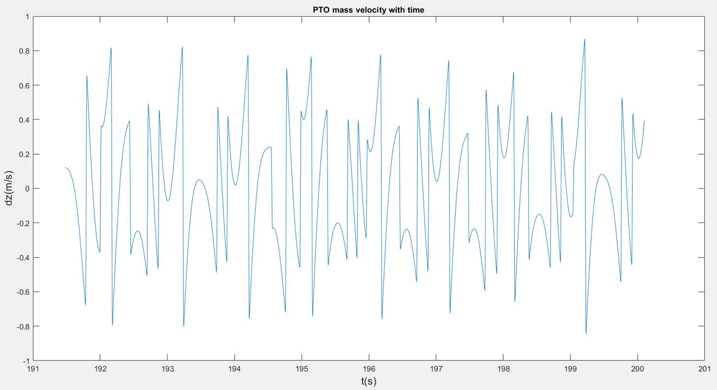
![]()
Absorbed
power, P = 0.3201 W
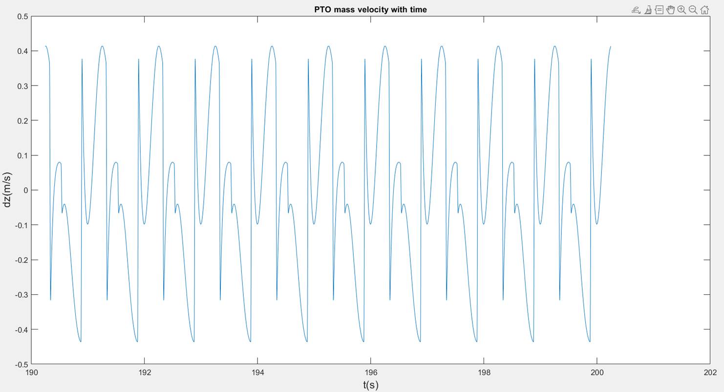
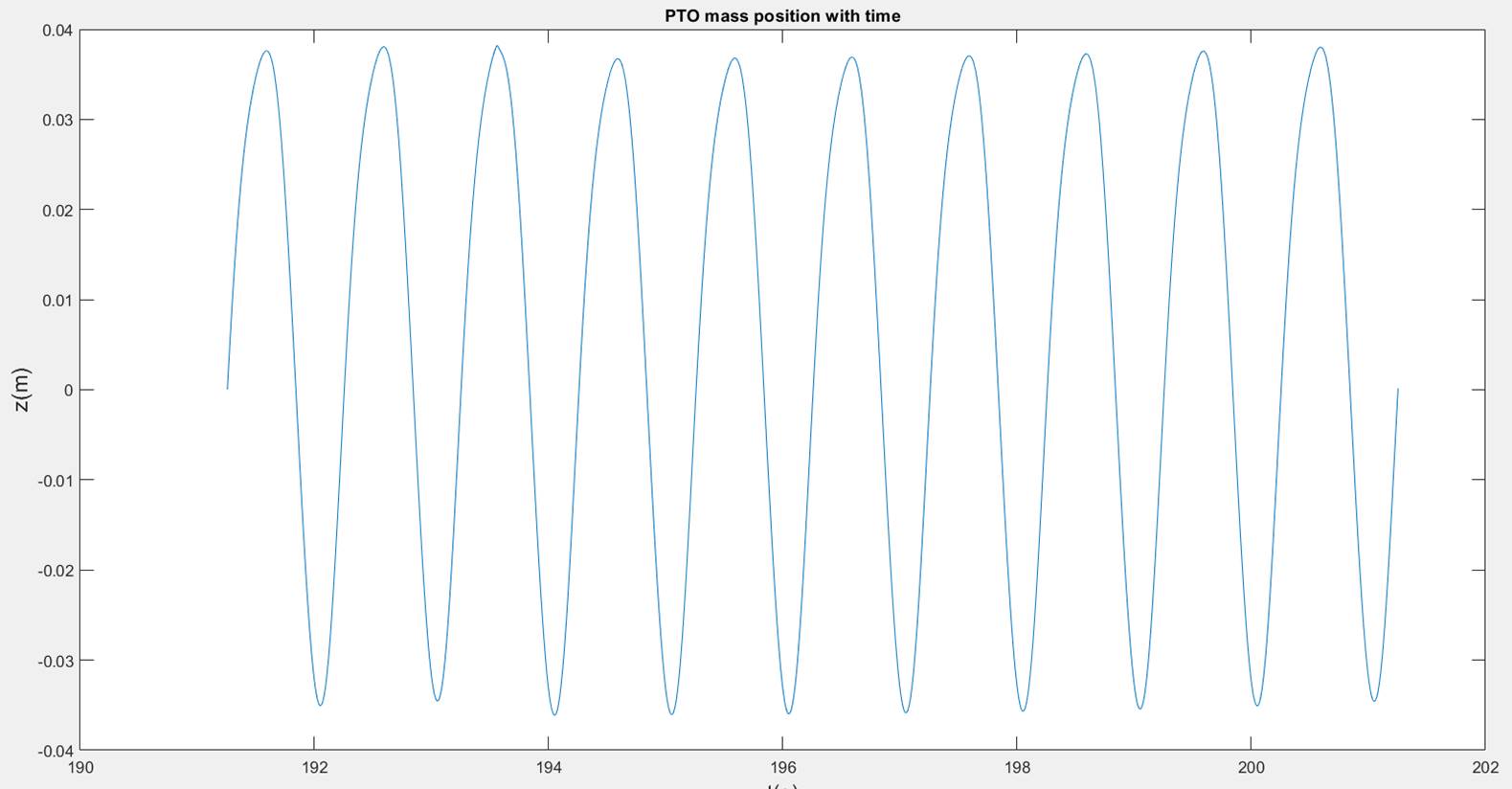
![]()
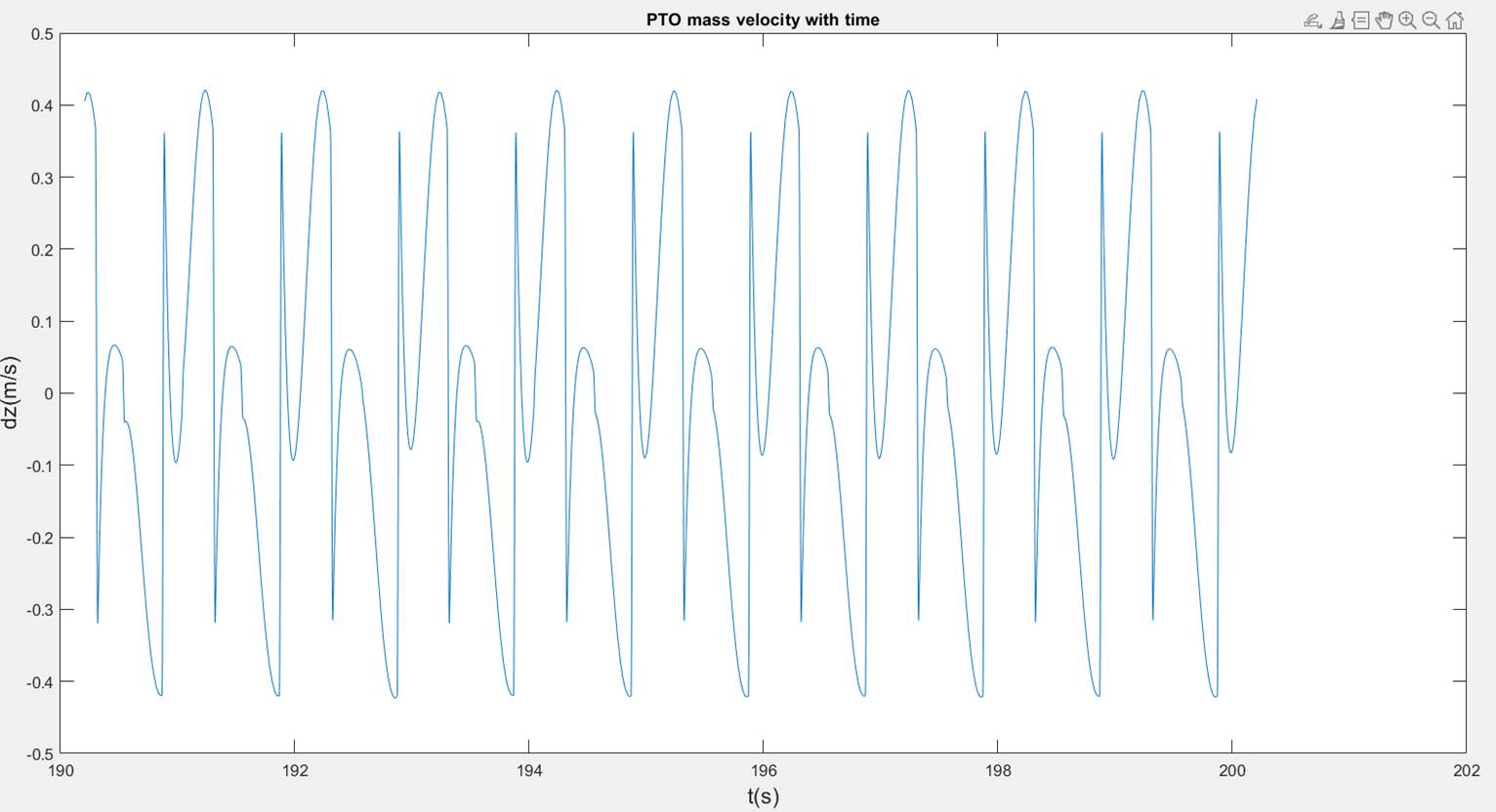
Absorbed
power, P = 0.3205 W
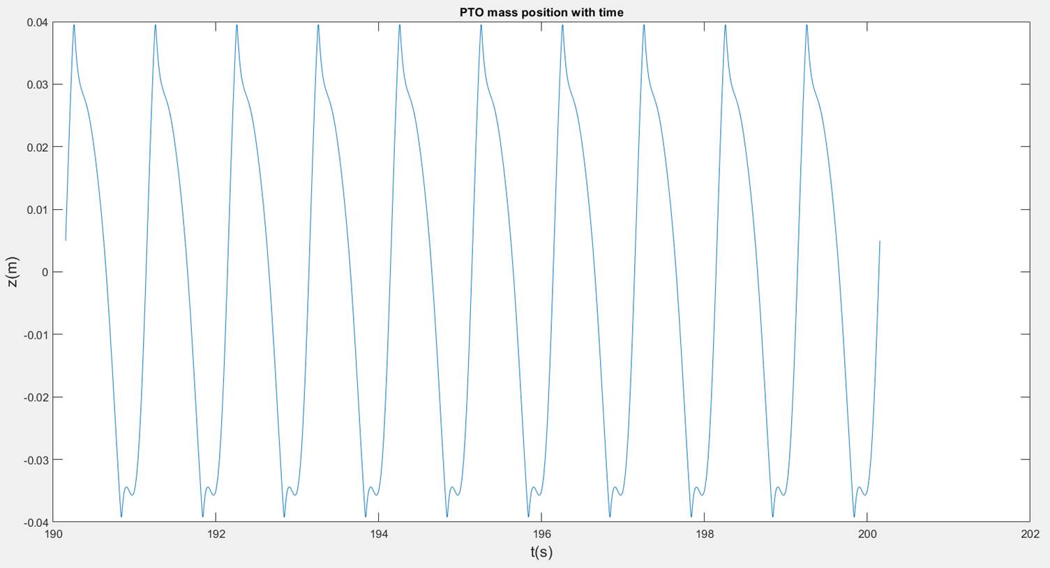
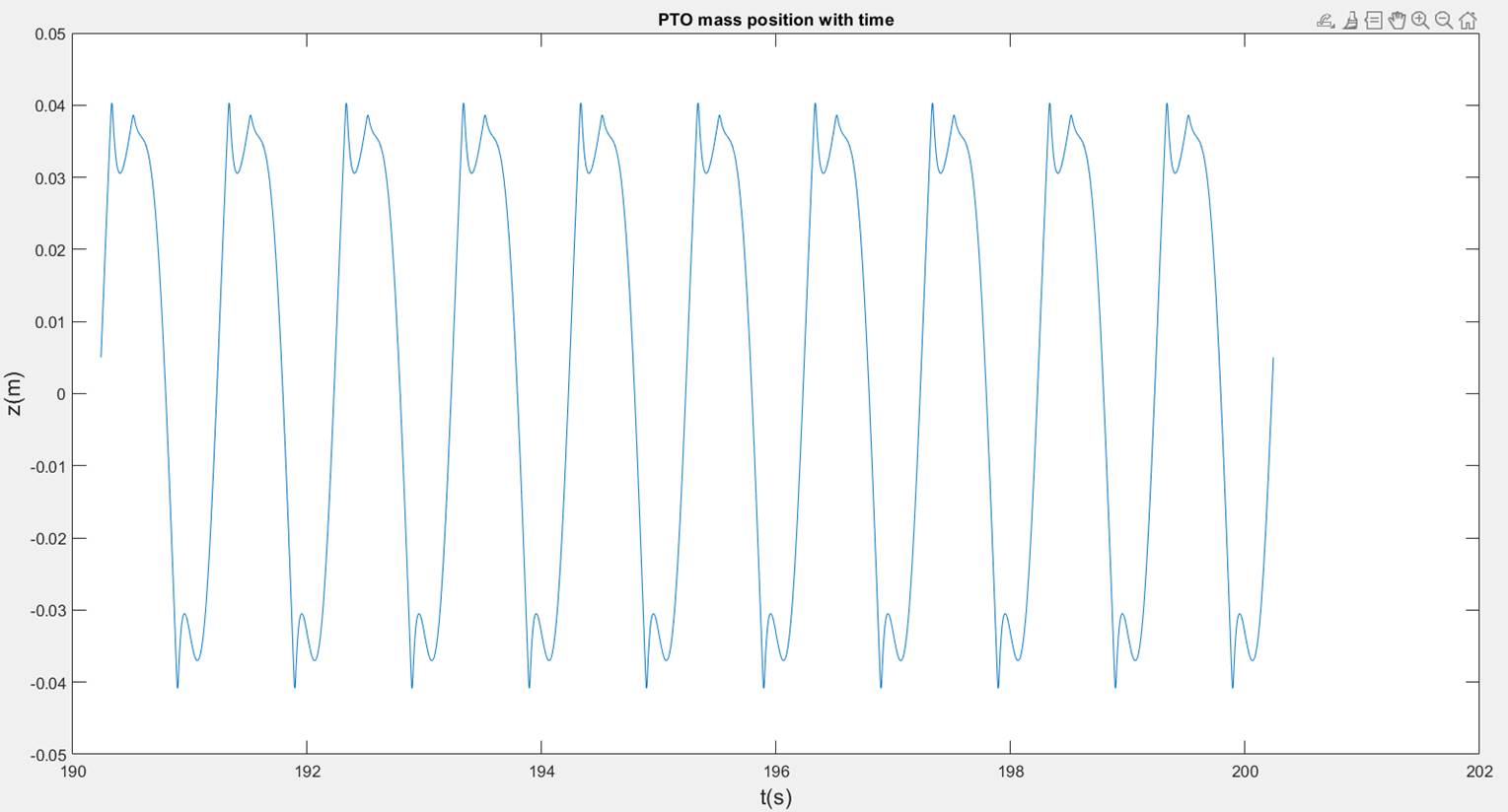
![]()
Absorbed
power, P = 0.2097 W
![]()
Absorbed
power, P = 0.1115 W
![]()
Absorbed
power, P = 0.2775 W
![]() Ns/m
Ns/m
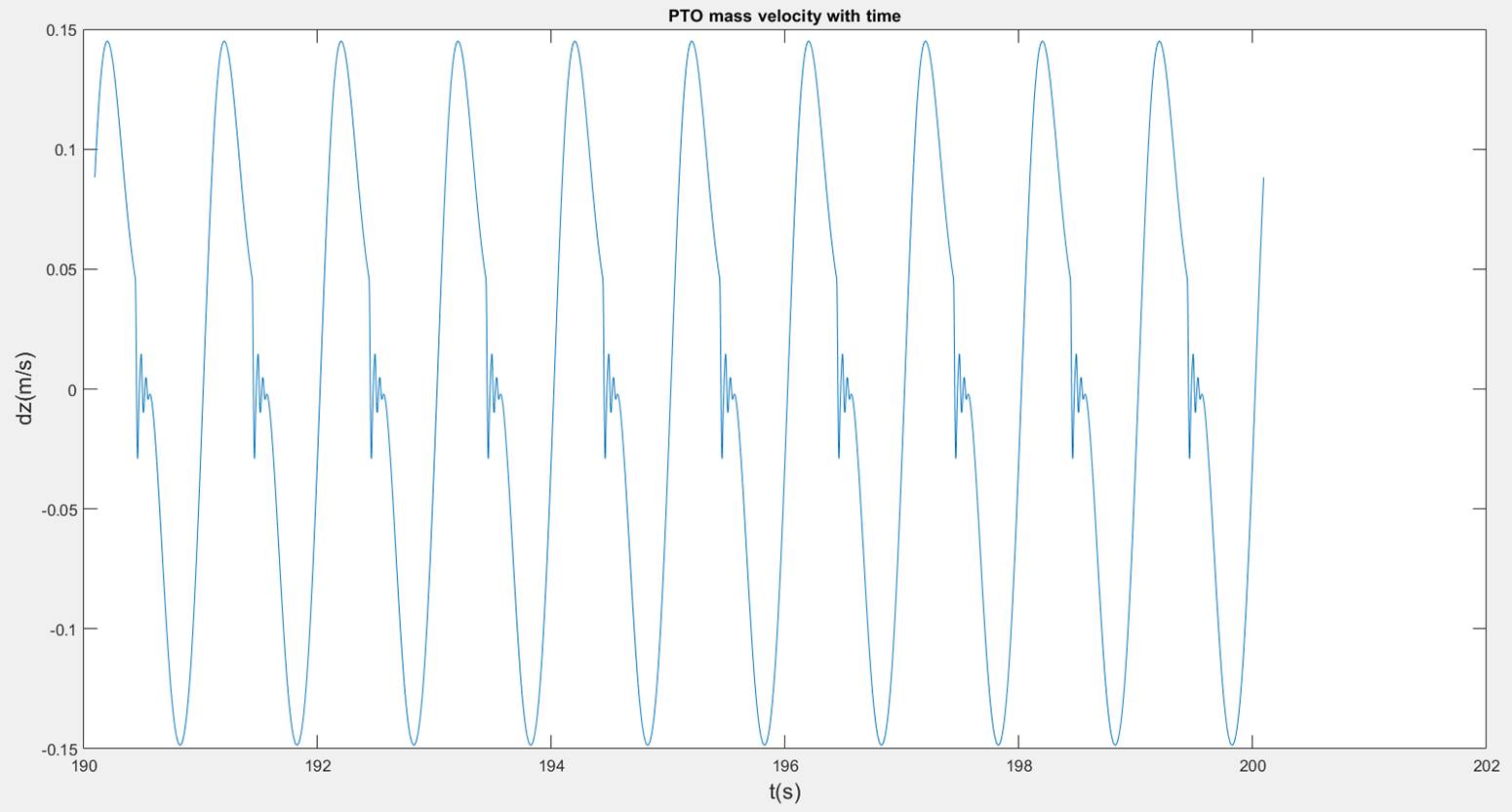
Absorbed
power, P = 0.1629 W
As you can see there is a deviation
between the experimental and mathematical model results. We believe the reason
for this is the quality of the camera. Due to budget issues, we utilized a
provided camera not equipped with the frame rate technology to analyze every
0.1 second. Either that or the video viewing software we used did not support
its capabilities. This is something to keep in mind in the future when other
senior design groups continue this work.
The objective
of the Testing and Validation stage is to prove our theories and methodologies in order to see if they work as intended, as well as to make
the necessary adjustments in order to achieve the most efficient AUV results.
This stage of the project Is currently a work in progress.
1. “Autonomous
Underwater Vehicle (AUV) Market,” Market Research Firm. [Online].
Available: https://www.marketsandmarkets.com/Market-Reports/autonomous-underwater-vehicles-market-141855626.html. [Accessed:
28-Jan-2021].
2. “Autonomous
Underwater Vehicle Manufacturers (AUV, UUV, ROV),” Unmanned Systems
Technology. [Online]. Available: https://www.unmannedsystemstechnology.com/category/supplier-directory/platforms/uuv-manufacturers/. [Accessed:
28-Jan-2021].
3. “Autonomous
underwater vehicles,” MBARI, 23-May-2018. [Online].
Available: https://www.mbari.org/at-sea/vehicles/autonomous-underwater-vehicles/. [Accessed:
28-Jan-2021].
4. “Comet-300
AUV,” RTSYS, 13-Jan-2021. [Online]. Available: https://rtsys.eu/comet-300-auv. [Accessed:
28-Jan-2021].
5. “SEARAPTOR
AUV,” ProductPage. [Online].
Available: http://www.teledynemarine.com/searaptor-auv?ProductLineID=15. [Accessed:
28-Jan-2021].
6. T. Baoqiang and J. Yu, “Current status and prospects of
marine renewable energy applied in ocean robots,” International Journal
of Energy Research, vol. 43, no. 6, pp. 2016–2031, Jan. 2019.
7. Bellingham,
J. (2009). Platforms: Autonomous underwater vehicles. Encyclopedia of
Ocean Sciences, 159-169. doi:10.1016/b978-0-12-813081-0.00730-8
8. http://web.mit.edu/12.000/www/m2005/a2/finalwebsite/equipment/robotics/structure.shtml
9. A. M.
Bradley, M. D. Feezor, H. Singh, and F. Y. Sorrell,
“Power Systems for Autonomous Underwater Vehiclesa,” IEEE
JOURNAL OF OCEANIC ENGINEERING, vol. 26, no. 4, pp. 526–536, Oct. 2001.
10. Author Logan
Mock-Bunting. (2015, November 25). The many challenges of underwater
communication. Retrieved February 25, 2021, from https://schmidtocean.org/cruise-log-post/the-many-challenges-of-underwater-communication/
11. Mange, V.,
Shah, P., & Kothari, V. (2019, June). Autonomous underwater vehicle:
Electronics and software ... Retrieved February 25, 2021, from https://www.irjet.net/archives/V6/i6/IRJET-V6I6689.pdf
12. Ewachiw, M. A., Jr.
(2014, June). Design of an autonomous underwater vehicle (auv)
charging ... Retrieved February 25, 2021, from https://apps.dtic.mil/dtic/tr/fulltext/u2/a610285.pdf
13. ROV FAQs.
(2021, January 28). Retrieved February 25, 2021, from https://schmidtocean.org/education/rov-faqs/
14. Ashish. “How
Does A Submarine Dive,
Resurface And Navigate Underwater? " Science ABC.” Science
ABC, 3 Dec. 2019, www.scienceabc.com/innovation/how-does-a-submarine-dive-resurface-and-navigate-underwater.html.
15. Hyakudome, Tadahiro. “Design of Autonomous Underwater Vehicle - Tadahiro Hyakudome,
2011.” SAGE Journals, journals.sagepub.com/doi/10.5772/10536.
16. Yun Hae Kim, Young Dae Jo, Sung Youl Bae and Seok Jin Sin,
"Material design of Al/CFRP hybrid composites for the hull of autonomous
underwater vehicle," OCEANS'10 IEEE SYDNEY, Sydney, NSW, Australia, 2010,
pp. 1-5, doi: 10.1109/OCEANSSYD.2010.5603587.
17. Structure.
[Online]. Available: http://web.mit.edu/12.000/www/m2005/a2/finalwebsite/equipment/robotics/structure.shtml.
[Accessed: 09-Mar-2021].
18. E.
Delory and J. Pearlman, Eds., “Chapter 5 - Innovative
Sensor Carriers for Cost-Effective Global Ocean Sampling,” in Challenges
and Innovations in Ocean In Situ Sensors,
Elsevier, pp. 173–288.
19. Author
Logan Mock-Bunting, “The Many Challenges of Underwater Communication,” Schmidt
Ocean Institute, 25-Nov-2015. [Online]. Available: https://schmidtocean.org/cruise-log-post/the-many-challenges-of-underwater-communication/.
[Accessed: 09-Mar-2021].
20. “AUV
LAB – ODYSSEY CLASS HISTORY,” MIT Sea Grant. [Online].
Available: https://seagrant.mit.edu/auv-odyssey-class/.
[Accessed: 09-Mar-2021].
21. “Is
Lithium-ion the Ideal Battery?,” Advantages
& Limitations of the Lithium-ion Battery - Battery University.
[Online]. Available: https://batteryuniversity.com/learn/archive/is_lithium_ion_the_ideal_battery.
[Accessed: 09-Mar-2021].
22. F.
Aguirre, S. Vargas, D. Valdes, and J. Tornero, “State
of the Art of Parameters for Mechanical Design of an Autonomous Underwater
Vehicle,” International Journal of Oceans and Oceanography , vol. 11, no. 1, pp. 89–103,
2017.
23. Yang, Y.,
2021, ‘Weekly Faculty Advisor Meetings’
24. N.
Townsend, “In situ results from a new energy scavenging system for an
autonomous underwater vehicle,” OCEANS 2016 MTS/IEEE Monterey, 2016.
This is a summary of important Senior
Design files, click on each to open in a different window.
SDI
REVIEWS
R2
RN
MIDTERM
PRESENTATION
FINAL
PRESENTATION
REPORT
SDII
REVIEWS
R1
R2
RN
MIDTERM
PRESENTATION
FINAL
THIS WEBSITE